Device for injecting a viscous material into a hard tissue

a technology of viscous material and hard tissue, applied in the field of injection biomechanics, can solve the problems of loss of density and strength of the trabecular bone, increased risk of so-called fragility fracture, and increased risk of neurological deficit or damage, and achieve the effect of high viscosity

Inactive Publication Date: 2007-08-09
BECKMAN LORNE +2
View PDF27 Cites 62 Cited by
  • Summary
  • Abstract
  • Description
  • Claims
  • Application Information

AI Technical Summary

Benefits of technology

[0014] It is therefore an aim of the present invention to provide a device for injecting a relatively high viscous material into hard tissue surrounded by soft tissue in an animal body whereby the injection of the high viscous material is facilitated.
[0015] Therefore, in accordance with the present invention, there is provided a device for injecting a relatively high viscous material into hard tissue surrounded by soft tissue in an animal body. The device comprising an elongated tubular member having a proximal section defining a syringe chamber and a distal section defining a cannula, the cannula having an inside diameter, and an outside diameter and a length sufficient for insertion into the hard tissue, the proximal section defining the syringe chamber having an inside diameter greater than the inside diameter of the cannula, the proximal section adapted to be inserted in the soft tissue, the cannula having a bore communicating with the syringe chamber, the syringe chamber adapted to receive a syringe containing the high viscous material for injection through the bore into the hard tissue whereby injection of the high viscous material is facilitated.
[0017] Further in accordance with the present invention, there is provided an injection system for injection of a relatively high viscous material into hard tissue surrounded by soft tissue in an animal body. The injection system comprising an elongated tubular member having a proximal section defining a syringe chamber and a distal section defining a cannula, the cannula having an inside diameter and an outside diameter and a length sufficient for insertion into the hard tissue, the proximal section defining the syringe chamber having an inside diameter greater than the inside diameter of the cannula, the proximal section adapted to be inserted in the soft tissue, the cannula having a bore communicating with the syringe chamber, and a syringe fitted for insertion within the syringe chamber of the proximal section, the syringe having an open end for communicating with the bore of the cannula, the syringe adapted for containing the high viscous material to be injected through the open end and the bore into the hard tissue respectively whereby injection of the high viscous material is facilitated.
[0018] Still in accordance with the present invention, there is provided a method for injecting a viscous material through hard tissue surrounded by soft tissue in an animal body. The method comprising the steps of providing an elongated tubular member comprising a distal section defining a cannula adapted to be inserted into hard tissue with minimal damage, and a proximal section defining a syringe chamber having larger outer and inner diameters than the cannula, inserting the cannula into the hard tissue, so that the proximal section remains outside of the hard tissue but at least partially within the soft tissue, inserting a syringe pre-filled with the viscous material into the syringe chamber, and using the syringe to inject the viscous material into the hard tissue through the cannula.

Problems solved by technology

Trabecular bone, therefore, loses density and strength and becomes more susceptible to so-called fragility fractures.
Vertebral fragility fractures often occur, resulting in chronic pain, progressive deformity and possibly even neurological deficit or damage.
The cement, once hardened, becomes a permanent reinforcement of the vertebral body and usually drastically diminishes the pain experienced by the patient.
Consequently, the procedure may have to be abandoned because the required injection pressure to continue the injection has become too high to be manually applied.
However, a high injection pressure increases the risk of separation of the cement into two phases (i.e., liquid and powder) while the high pressure applicator reduces the tactile feedback of the surgeon and limits the surgeon's ability to accurately control cement flow.
However, this type of cannula does not address the injection pressure limitations that exist, since the proposed system requires a high pressure applicator generating pressures up to 4000 psi (over 27500 KPa).
While the patents also suggest a cannula geometry to reduce the pressure requirements, the injection pressures obtained are still well over the limit of what a surgeon can generate manually using a syringe.

Method used


Image

  • Device for injecting a viscous material into a hard tissue
  • Device for injecting a viscous material into a hard tissue
  • Device for injecting a viscous material into a hard tissue

Examples


experiment a

Method

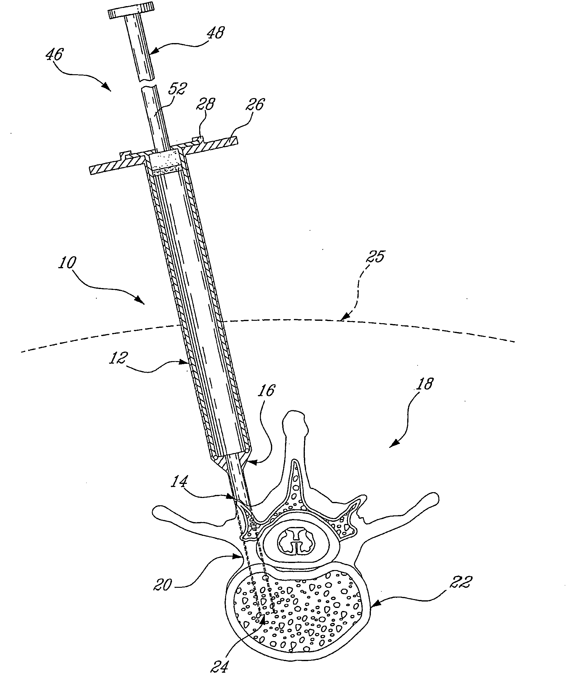
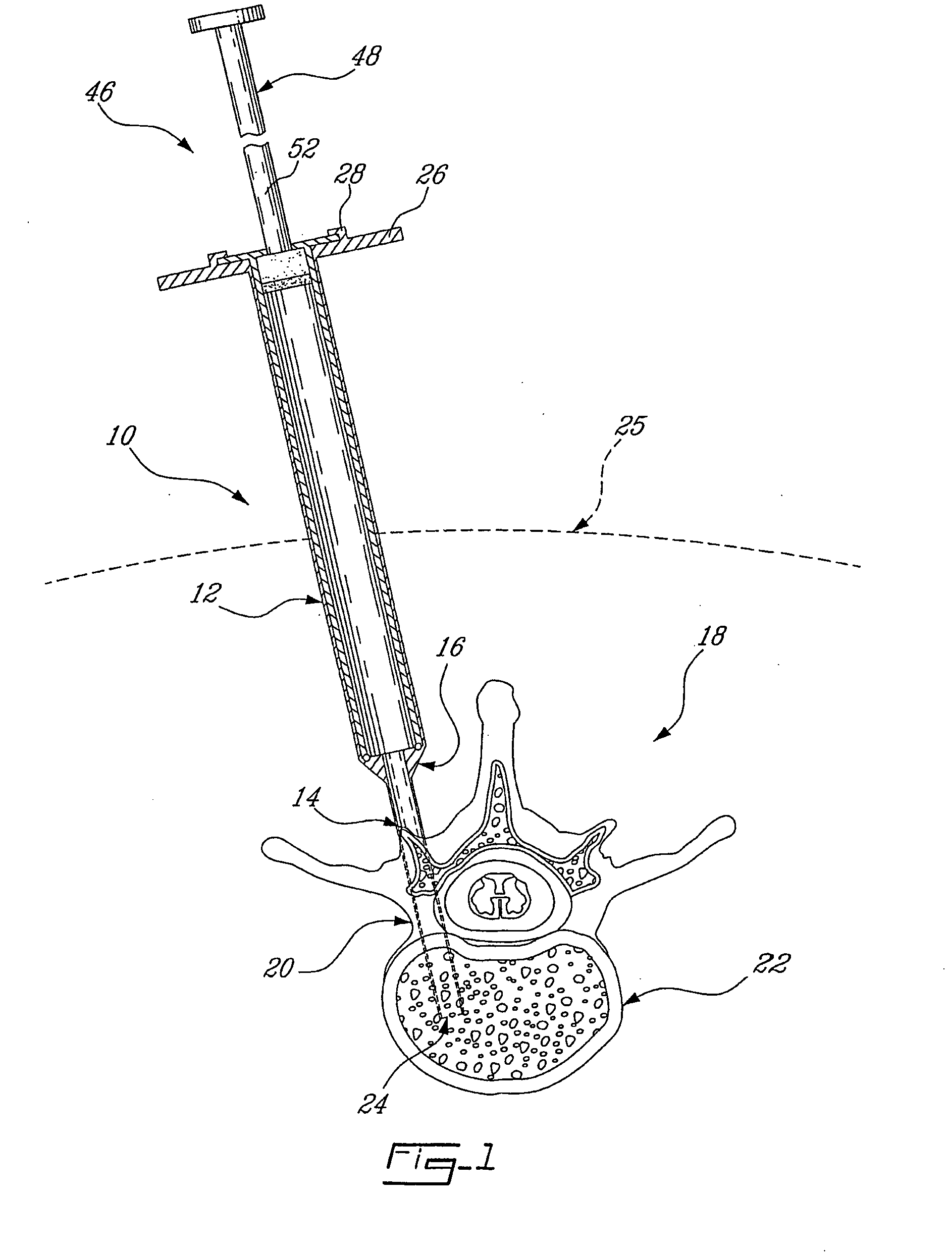
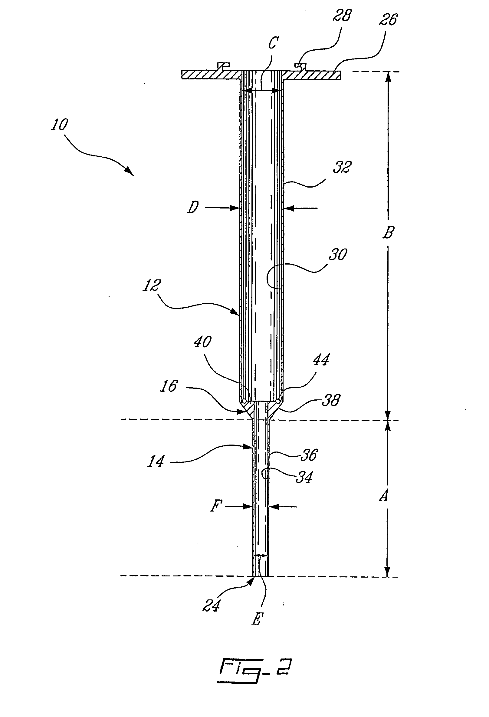
[0056] Three different elongated tubular members were tested. A first tubular member was a traditional single stage inner diameter 8 gauge cannula (inner diameter of 3.125 mm, length of 120 mm). Second and third tubular members were designed according to the present invention having a staged inner diameter as shown in FIG. 1. Thus, the distal end defining the cannula having an inner diameter E equal to the inner diameter of the 8-gauge cannula, i.e. 3.125 mm. The syringe chamber 12 having a length B of 80 mm and a cannula 14 length A of 40 mm. The second tubular member featured a syringe chamber 12 inner diameter C of approximately 6.35 mm for a relative increase of about 2 or 200% compared to the inner diameter E of the cannula thereof. The third tubular member featured a syringe chamber inner diameter C of approximately 9.525 mm for a relative increase of approximately 3 or 300% compared to the inner diameter E of the cannula thereof.

[0057] A thick-viscous silicone oil of...


PUM


Abstract

An injection system for injection of a relatively high viscous material into hard tissue surrounded by soft tissue in an animal body. The injection system comprising an elongated tubular member having a proximal section defining a syringe chamber and a distal section defining a cannula. The cannula having an inside diameter and an outside diameter and a length sufficient for insertion into the hard tissue. The proximal section defining the syringe chamber having an inside diameter greater than the inside diameter of the cannula, the proximal section adapted to be inserted in the soft tissue. The cannula having a bore communicating with the syringe chamber. The injection system comprising a syringe fitted for insertion within the syringe chamber of the proximal section. The syringe having an open end for communicating with the bore of the cannula. The syringe adapted for containing the high viscous material to be injected through the open end and the bore into the hard tissue respectively whereby the injection of the high viscous material is facilitated.

Description

CROSS-REFERENCE TO RELATED APPLICATIONS [0001] This is a continuation of International Application No. PCT / CA2005 / 000222 filed Feb. 18, 2005, designating the United States, which itself claims priority on U.S. provisional application 60 / 545,282 which was filed Feb. 18, 2004, the specifications of both of which are incorporated herein by reference.BACKGROUND OF THE INVENTION [0002] The present invention relates to the field of injection biomechanics, and more particularly to a device for injecting a relatively high viscous material into a hard tissue. [0003] Osteoporosis is caused by a gradual loss of bone minerals along with a progressive structural change of trabecular bone (increased porosity, loss of horizontal struts, etc.). Trabecular bone, therefore, loses density and strength and becomes more susceptible to so-called fragility fractures. Vertebral fragility fractures often occur, resulting in chronic pain, progressive deformity and possibly even neurological deficit or damage...

Claims


Application Information

Patent Timeline
Patent Type & Authority Applications(United States)
IPC IPC(8): A61F2/00A61B17/00A61B17/70A61B17/88A61F2/46
CPCA61B17/00234A61F2002/4635A61B17/8822A61B17/8816
Inventor BECKMAN, LORNEBAROUD, GAMALSTEFFEN, THOMAS
Owner BECKMAN LORNE
Why Eureka
Try Eureka