Permanent magnet synchronous machine, and pressing or extrusion machine including permanent magnet synchronous machine

a permanent magnet and synchronous machine technology, applied in the direction of dynamo-electric machines, magnetic circuit rotating parts, magnetic circuit shape/form/construction, etc., can solve the problems of magnetic saturation probability, torque reduction, flux reduction of permanent magnets, etc., and achieve the effect of expanding the high-speed operation range without reducing torqu

Inactive Publication Date: 2011-10-06
HITACHI LTD
View PDF11 Cites 10 Cited by
  • Summary
  • Abstract
  • Description
  • Claims
  • Application Information

AI Technical Summary

Benefits of technology

[0027]A permanent magnet synchronous machine according to the present invention, and a pressing machine or an extrusion machine using the permanent magnet synchronous machine, are capable of expanding a high-speed operation range without reducing torque.

Problems solved by technology

As described above, while a method of reducing inductance is effective for expanding a high-revolving speed range of a permanent magnet synchronous electric machine, there is a dilemma in that a use of a rare-earth magnet increases a likelihood of magnetic saturation when slits are provided on a rotor in order to reduce inductance, thereby causing a decrease in flux generated by a permanent magnet as well as a decrease in torque.

Method used


Image

  • Permanent magnet synchronous machine, and pressing or extrusion machine including permanent magnet synchronous machine
  • Permanent magnet synchronous machine, and pressing or extrusion machine including permanent magnet synchronous machine
  • Permanent magnet synchronous machine, and pressing or extrusion machine including permanent magnet synchronous machine

Examples


first embodiment

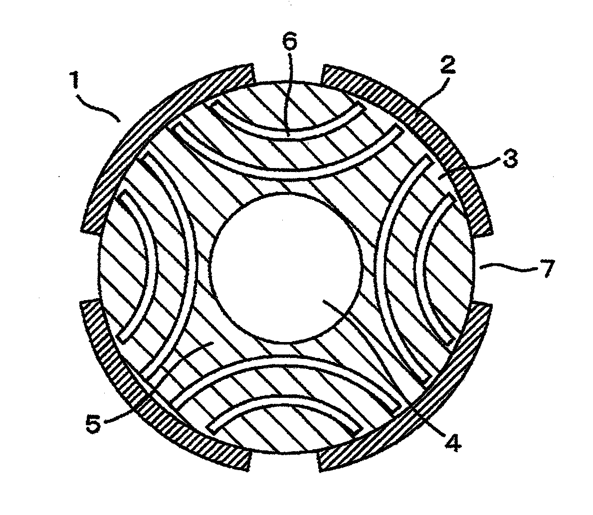
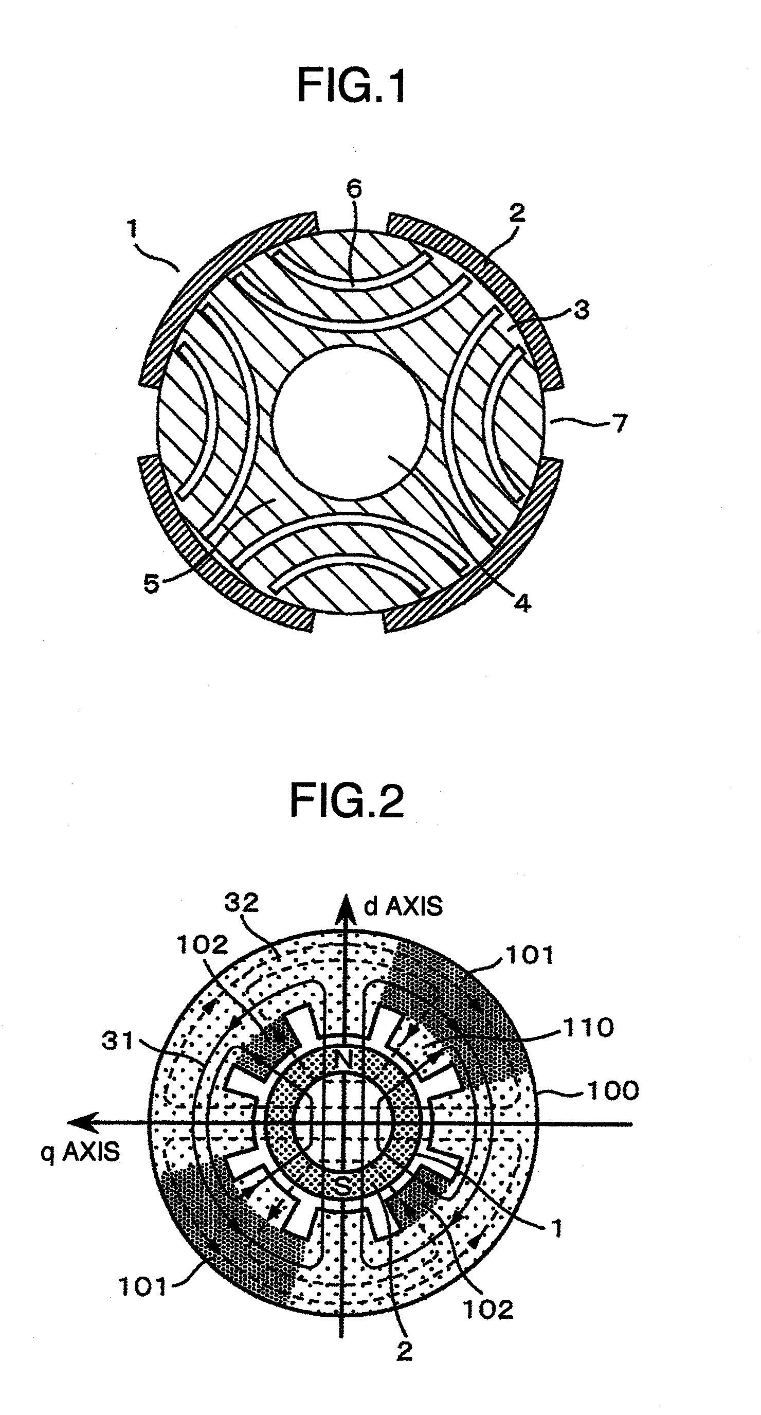
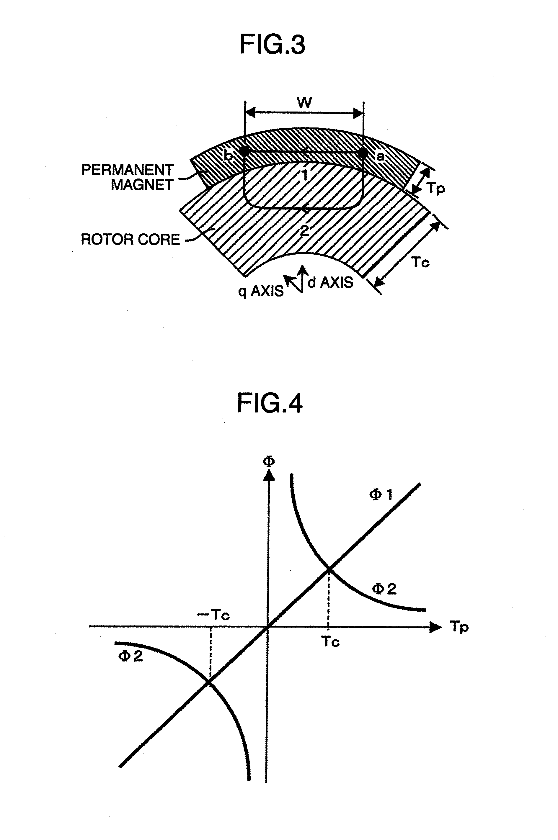
[0041]FIG. 1 is a radial cross-sectional view of a rotor of a permanent magnet synchronous electric machine according to a first embodiment of the present invention. In addition, FIG. 2 is a schematic diagram of magnetic flux lines on a radial cross section of a permanent magnet synchronous electric machine according to the first embodiment of the present invention, FIG. 5 is a radial cross-sectional view of a rotor for describing a width of a permanent magnet and a width of a slit provided on a rotor core illustrated in FIG. 1, and FIG. 4 illustrates a relationship diagram of a slit width, no-load back EMF E0, torque Mp, and quadrature axis inductance Lq according to the present embodiment.

[0042]In FIG. 1, a rotor 1 is constituted by lamination steel and transfers power to outside via an output shaft inserted into a shaft hole 4. Permanent magnets 2 are arranged on a radial surface of a rotor core 5 so as to form a quadrupole. A reduction in inductance can be achieved by providing ...

second embodiment

[0073]FIG. 11 is a radial cross-sectional view of a rotor of a permanent magnet synchronous electric machine according to a second embodiment of the present invention. In FIG. 11, like components to FIG. 1 will be denoted by like reference characters and redundant descriptions will be avoided.

[0074]The configuration in FIG. 11 differs from FIG. 1 in that permanent magnets 2 are arranged so as to form an octapole, four slits 6 provided per magnetic pole are individually defined as 6a, 6b, 6c, and 6d, widths of the slits in a direction perpendicular to an extending direction of the slits are respectively defined as Wsl1, Wsl2, Wsl3, and Wsl4, and a circumferential width of an inner circumferential surface of a permanent magnet in contact with an outer circumferential surface of a rotor core 5 is defined as Wpm. A sum total Wsl of widths of the slits 6a to 6d can be expressed in a same manner as formula (7).

[0075]As described above, even with a sextupole machine, an octapole machine, a...


PUM


Abstract

To provide a permanent magnet synchronous machine capable of expanding a high-speed operation range without reducing torque, and a pressing machine or an extrusion machine using the permanent magnet synchronous machine. In order to achieve the object described above, the present invention provides a permanent magnet synchronous electric machine having at least one permanent magnet on a radial surface of a rotor core, the permanent magnet having a rotor constituting a field pole, wherein a plurality of slits constituted by nonmagnetic material is provided on a core part between adjacent permanent magnets with opposite magnetic polarities of the rotor. According to the present invention, expansion of a high-speed operation range can be achieved without reducing torque.

Description

BACKGROUND OF THE INVENTION[0001]The present invention relates to a permanent magnet synchronous machine, and a pressing or extrusion machine using the permanent magnet synchronous machine.[0002]When a permanent magnet synchronous electric machine is rotated at high speed, a voltage drop by inductance increases in proportion to the rotational speed. Therefore, an upper limit of the rotational speed is set in order to prevent a shortage of input voltage. As disclosed in FIG. 4 of JP-A-2002-84690, there is a technique that aims to expand a high-revolving speed range by providing slits in a pole shoe on an outer side and in a pole shoe on an inner side of a permanent magnet embedded in a rotor so as to reduce inductance.[0003]However, with a configuration described in the conventional technique, a radial length of the permanent magnet is greater than a radial length of a rotor core, resulting in an extremely high magnetic resistance. Configurations using such a thick-walled permanent m...

Claims


Application Information

Patent Timeline
Patent Type & Authority Applications(United States)
IPC IPC(8): H02K1/27B30B1/00
CPCH02K1/246H02K2213/03H02K1/278
Inventor TAKAHASHI, AKESHIWAKUI, SHINICHI
Owner HITACHI LTD
Why Eureka
Try Eureka