
Oil-water separation device for treating oil-containing wastewater

An oil-water separation device and oil-water separation technology, applied in the direction of grease/oily substance/suspton removal device, filtration separation, separation method, etc., can solve the problem of increased cost of oily sewage treatment, easy clogging of oil-accumulated filter elements, increased labor intensity, etc. Problems, achieve good oil-water separation effect, improve oil removal effect, and reduce labor intensity

Inactive Publication Date: 2011-03-09
ZHOUSHAN ZHONGBANG ENERGY SAVING TECH
View PDF1 Cites 0 Cited by
  • Summary
  • Abstract
  • Description
  • Claims
  • Application Information

AI Technical Summary

Problems solved by technology

However, the current oil-water separation devices using oil-accumulating filter elements are too simple in structure, resulting in poor oil separation effect, and the oil-accumulating filter elements are easy to block, resulting in increased treatment costs and labor intensity for oily sewage.

Method used


Image

  • Oil-water separation device for treating oil-containing wastewater
  • Oil-water separation device for treating oil-containing wastewater
  • Oil-water separation device for treating oil-containing wastewater

Examples


Embodiment 2

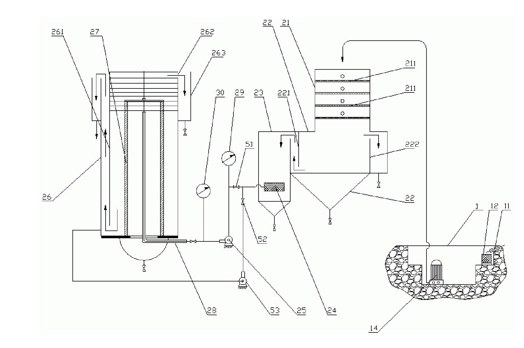
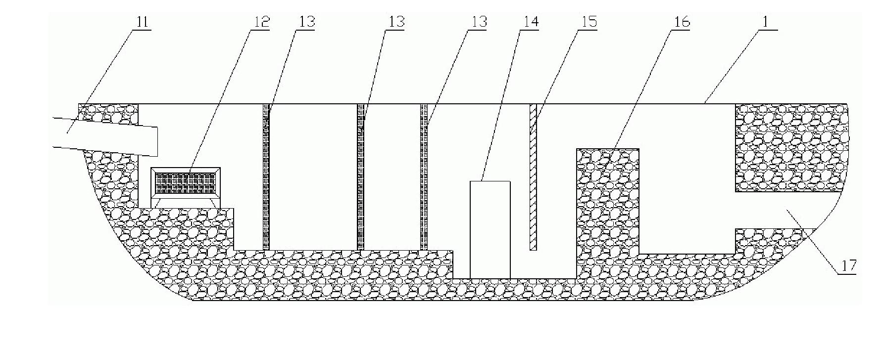
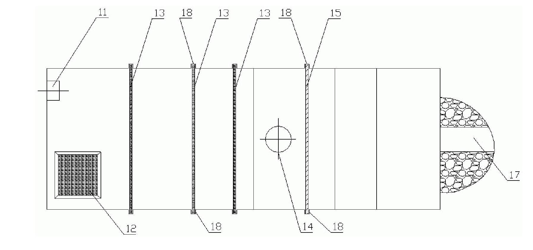
[0047] Such as Figure 4 As shown, an oil-water separation device for treating oily wastewater has a multi-stage oil-water separation structure as a whole, including a sewage filter tank 1 and an oil-water separation host. This embodiment is basically the same as Embodiment 1, the difference is:

[0048] The I-stage oil tank 22 is provided with a dividing plate 221, an oil spill port 223 and an inner tank body 224, and the upper end of the dividing plate 221 is connected with the tank body of the I-stage oil tank 22, and the bottom of the dividing plate 221 is connected with the I-stage oil tank 22. A drainage opening is provided between the oil tanks 22 tank bodies, and the oil overflow port 223 is located at the top of the I-stage oil tank 22, and the inner tank body 224 is a cylinder with an open top, and the bottom of the inner tank body 224 is connected to the I-stage oil tank 22. The tank body is connected, the sewage pump 14 is connected with the upper part of the filt...


PUM


Abstract

The invention provides an oil-water separation device for treating oil-containing wastewater with the advantages of difficult blockage of filter element, long service life, low labor intensity and low treatment cost, which is characterized in that: the oil-water separation device has a multi-level oil-water separation structure which comprises a sewage filter tank and an oil-water separation mainframe, wherein the sewage filter tank is provided with a filter basket for primary filtration, a filter screen and a sewage pump; and the oil-water separation mainframe mainly comprises a I-level oil separation device and a II-level oil separation device. The oil-water separation device can be used for collecting and separating sump oil in the drainage of a kitchen, effectively solves the problem of secondary pollution caused by a dining table, and has the advantages of simple and reasonable structure, good oil-water separation effect, and suitability for oil-water separation of sewage in kitchens of big and small hotels in cities and towns and cruise ships.

Description

technical field [0001] The invention relates to a device for discharging sewage and separating oil and water from kitchens such as canteens, hotels and restaurants, and belongs to the field of water treatment. Background technique [0002] With the improvement of people's living standards, the number of hotels, restaurants, and guesthouses has increased accordingly. The oil in the kitchen waste sewage discharge has not been separated and recycled, and it is directly discharged into the surrounding rivers and lakes, which is likely to cause blockage of sewer pipes and lead to serious water environment. pollute. It can be seen that separating and collecting the dirty oil in the kitchen drainage is an important measure to prevent water resources from being polluted, and effectively solves the secondary pollution caused by the dining table. [0003] At present, the method of removing oil from kitchen waste sewage generally adopts the method of grease trap. Its main disadvantage...

Claims


Application Information

Patent Timeline
Patent Type & Authority Patents(China)
IPC IPC(8): B01D36/00C02F1/40
Inventor 郑育兴包启胜赵子林
Owner ZHOUSHAN ZHONGBANG ENERGY SAVING TECH
Learn More