Thermoregulation and dehumidification type water loop heat pump unit

A technology of water ring heat pump and heat pump unit, which is applied in the direction of reversible cycle compressors, refrigerators, compressors, etc., and can solve problems such as applicability limitations

Inactive Publication Date: 2009-12-16
苏宇贵
View PDF0 Cites 33 Cited by
  • Summary
  • Abstract
  • Description
  • Claims
  • Application Information

AI Technical Summary

Problems solved by technology

[0002] A large number of heat pump units are used in room cooling and heating. Its structure is generally two heat exchangers, throttling elements, and compressors, which are connected through connecting pipes to form a refrigerant circulation loop. However, the existing heat pump units are common The function is cool...

Method used


Image

  • Thermoregulation and dehumidification type water loop heat pump unit
  • Thermoregulation and dehumidification type water loop heat pump unit
  • Thermoregulation and dehumidification type water loop heat pump unit

Examples


Embodiment 1

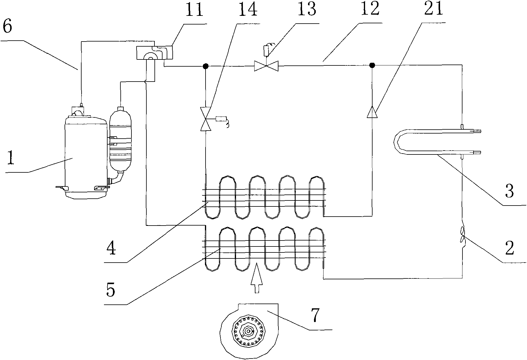
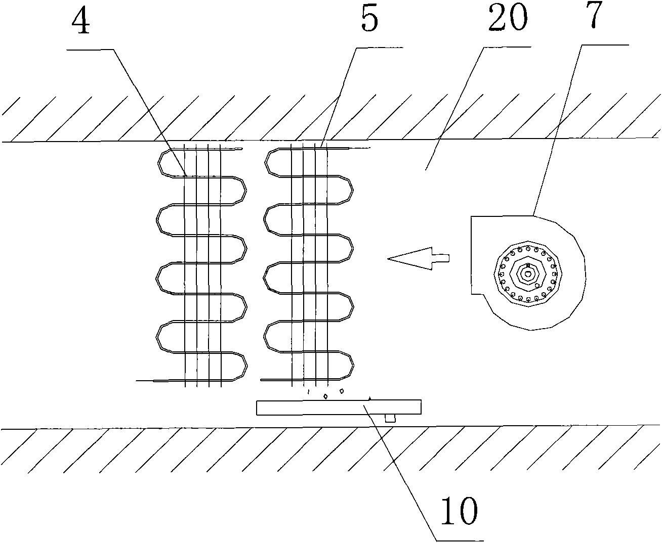
[0026] like figure 1 , figure 2 As shown, the temperature-regulating and dehumidifying water-loop heat pump unit includes a compressor 1, a throttling element 2, an indoor heat exchanger, an outdoor heat exchanger 3, a compressor 1, a throttling element 2, an indoor heat exchanger, The outdoor heat exchanger 3 is communicated with the connecting pipe 6 to form a heat exchange working medium circulation circuit; the indoor heat exchanger is two, namely the first indoor heat exchanger 4 and the second indoor heat exchanger 5, and the first indoor heat exchanger The heat exchanger 4, the second indoor heat exchanger 5, and the outdoor heat exchanger 3 are connected in series through the aforementioned connecting pipe 6; the first indoor heat exchanger 4 and the second indoor heat exchanger 5 are both wind-side heat exchangers and In the same indoor heat exchange air channel 20, a fan 7 is provided at the heat exchange air channel.

[0027] Wherein, the first indoor heat exchan...

Embodiment 2

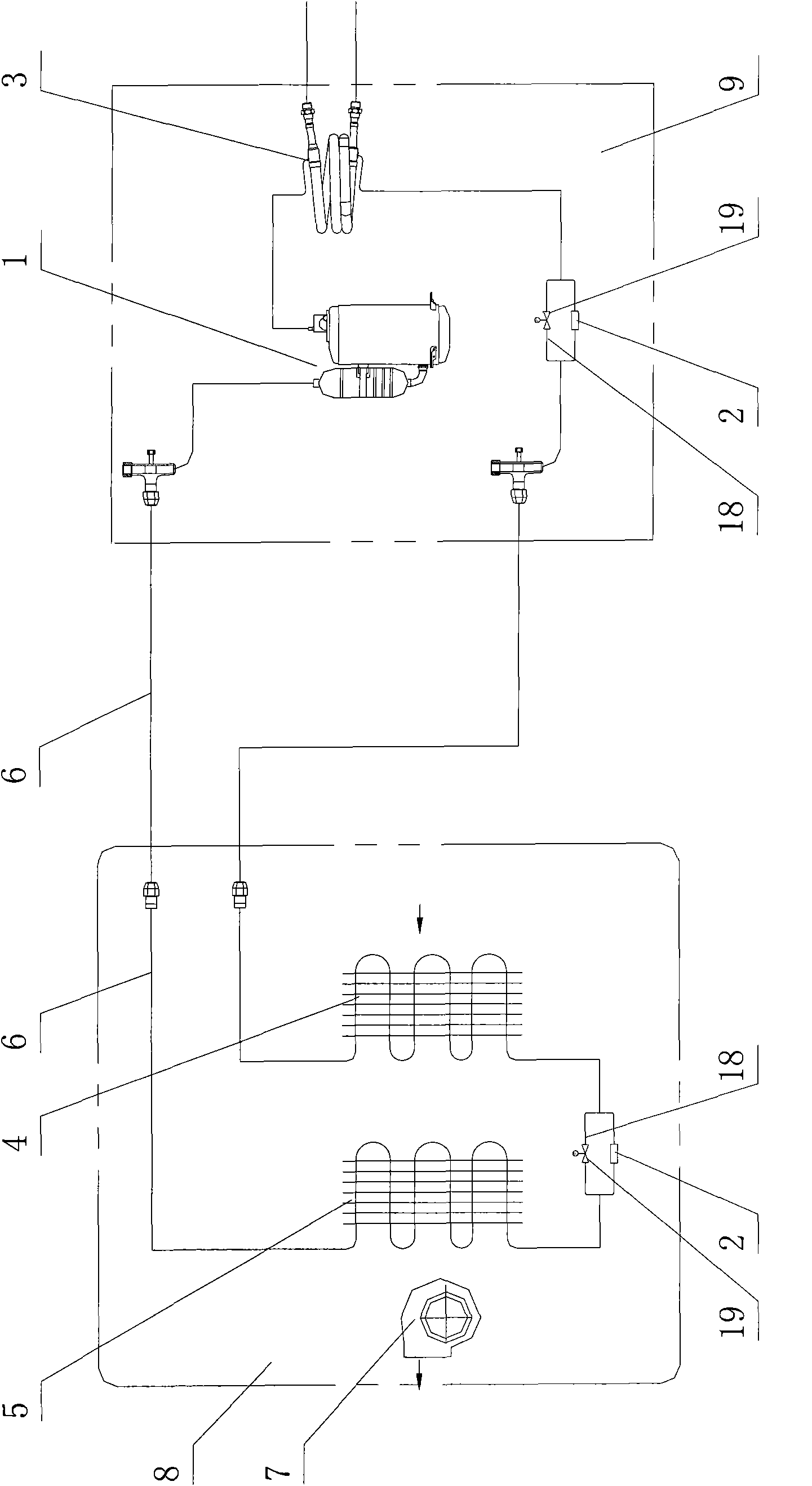
[0033] like image 3 As shown, in this embodiment, the heat pump unit is a split structure, which includes an indoor unit 8 and an outdoor unit 9, the compressor 1 and the outdoor heat exchanger 3 are arranged in the outdoor unit 9, the first indoor heat exchanger 4, the second The second indoor heat exchanger 5 is located in the indoor unit 8; the outdoor heat exchanger 3, the first indoor heat exchanger 4, and the second indoor heat exchanger 5 are connected in series; the outdoor heat exchanger 3 and the second indoor heat exchanger 5 They are respectively close to the exhaust end and the suction end of the compressor 1; there are two throttling elements 2, which are respectively arranged between the outdoor heat exchanger 3 and the first indoor heat exchanger 4 and between the first indoor heat exchanger 4 and the second indoor heat exchanger. Between the two indoor heat exchangers 5 , a throttle bypass pipe 18 is connected in parallel at both ends of the two throttle elem...

Embodiment 3

[0038] like Figure 4 As shown, compared with Embodiment 2 in this embodiment, the heat pump unit also includes a four-way valve 11, and the low-pressure port and high-pressure port of the four-way valve 11 communicate with the suction port and the exhaust port of the compressor 1 respectively. The two switching ports of the four-way valve 11 are in communication with the heat exchange pipeline; the flow direction of the heat-exchange working medium in the heat-exchange pipeline can be changed through the four-way valve 11, the principle is the same as that of Embodiment 1, and will not be repeated here. .


PUM


Abstract

The invention discloses a tthermoregulation and dehumidification type water loop heat pump unit, comprising a compressor, a throttling element, indoor heat interchangers and an outdoor heat interchanger; wherein, the compressor, the throttling element, the indoor heat interchanger and the outdoor heat interchanger are communicated by connection pipes to form a heat exchange working medium circulation loop; the indoor heat interchanger consists of a first indoor heat interchanger and a second heat interchanger; the first indoor heat interchanger, the second heat interchanger and the outdoor heat interchanger are communicated in series by the connection pipes; the first indoor heat interchanger and the second heat interchanger are both air side heat exchangers arranged in the same indoor heat exchange air duct, a fan is arranged at the heat exchange air duct. The water loop heat pump unit of the invention not only has the function of air-conditioning refrigeration but also the function of dehumidification at constant temperature; with more functions, the water loop heat pump unit has better adaptability.

Description

technical field [0001] The invention relates to a temperature regulation and dehumidification type water ring heat pump unit. Background technique [0002] A large number of heat pump units are used in room cooling and heating. Its structure is generally two heat exchangers, throttling elements, and compressors, which are connected through connecting pipes to form a refrigerant circulation loop. However, the existing heat pump units are common The function is cooling and heating. During the cooling process, due to the decrease in temperature, the water vapor in the air will condense to achieve the function of cooling and dehumidification. Dehumidification is carried out under certain conditions, but the existing heat pump unit cannot realize this function at all, and its applicability is limited. Contents of the invention [0003] The purpose of the present invention is to provide a temperature-regulating and dehumidifying water-loop heat pump unit. The present invention ...

Claims


Application Information

Patent Timeline
IPC IPC(8): F24F1/00F24F13/30F25B5/04F25B6/04F25B13/00F25B41/06F25B41/04F25B41/00F24F11/02
Inventor 苏宇贵
Owner 苏宇贵
Why Eureka
Try Eureka