High order temperature supplementary band gap reference circuit
A high-order temperature compensation and reference circuit technology, which is applied in the direction of adjusting electrical variables, control/regulation systems, instruments, etc., can solve the problems of complex high-order compensation circuits, large chip footprint, and limitations of high-order compensation technology, and achieve good results. The effect of process stability, high power supply rejection ratio, and high process stability
- Summary
- Abstract
- Description
- Claims
- Application Information
AI Technical Summary
Problems solved by technology
Method used
Image

Examples
Embodiment Construction
[0016] Below in conjunction with accompanying drawing, the technical scheme of invention is described in detail:
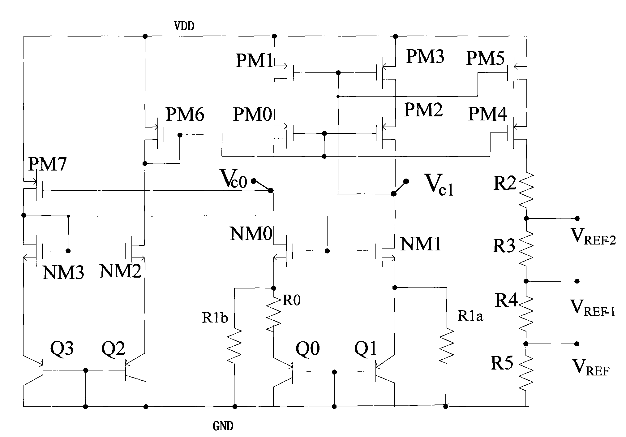
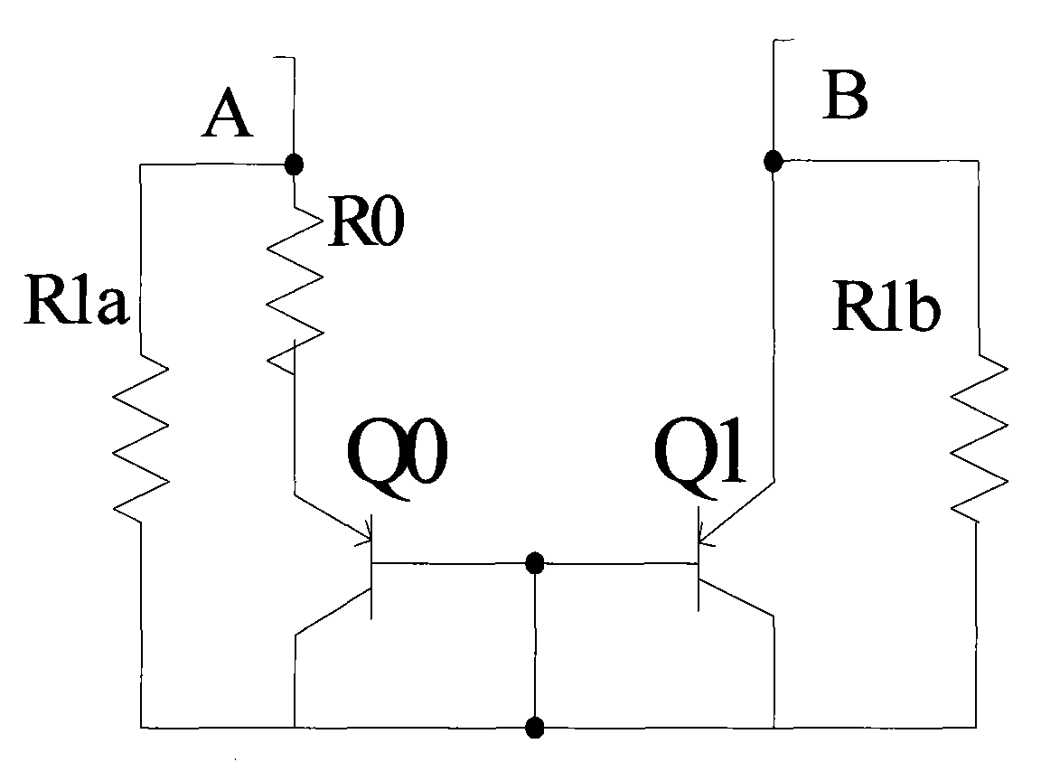
[0017] Depend on figure 1 In , if the current mirror in the reference main circuit is completely matched, and the currents in the two branches Q0 and Q1 are equal, then we can get:
[0018] V REF = ( V EB R 1 b + V T ln N R 0 ) · K · R REF = ( V EB + R 1 ...
PUM
 Abstract
Description
Claims
Application Information
PatSnap Eureka turns technology decisions into work you can execute. Powered by our Innovation Knowledge Graph, it runs expert workflows across engineering, life sciences, materials and intellectual property. Get your review-ready output in minutes.


