Cam limit switch

A technology of cam limit and switch, which is applied in the direction of contact drive mechanism, etc.

Active Publication Date: 2009-12-16
NINGBO WEILONG PORT MASCH CO LTD +1
View PDF0 Cites 2 Cited by
  • Summary
  • Abstract
  • Description
  • Claims
  • Application Information

AI Technical Summary

Problems solved by technology

[0004] The technical problem to be solved by the present invention is to provide a multi-stage transmission ratio cam limit switch with low transmission ratio in view of the problems existing in the existing cam limit switch

Method used


Image

  • Cam limit switch
  • Cam limit switch
  • Cam limit switch

Examples


Embodiment Construction

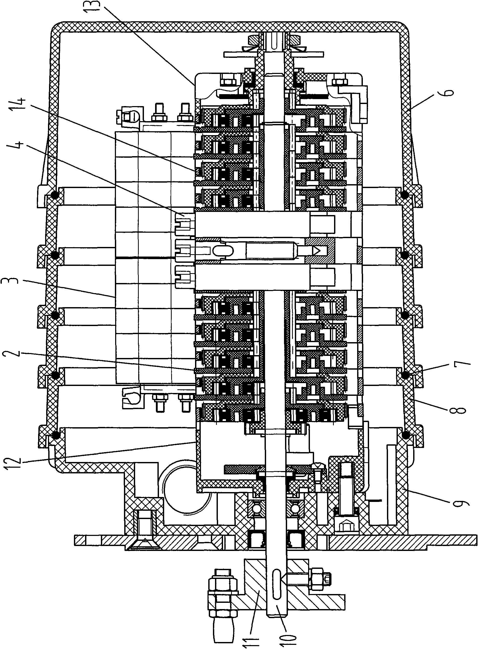
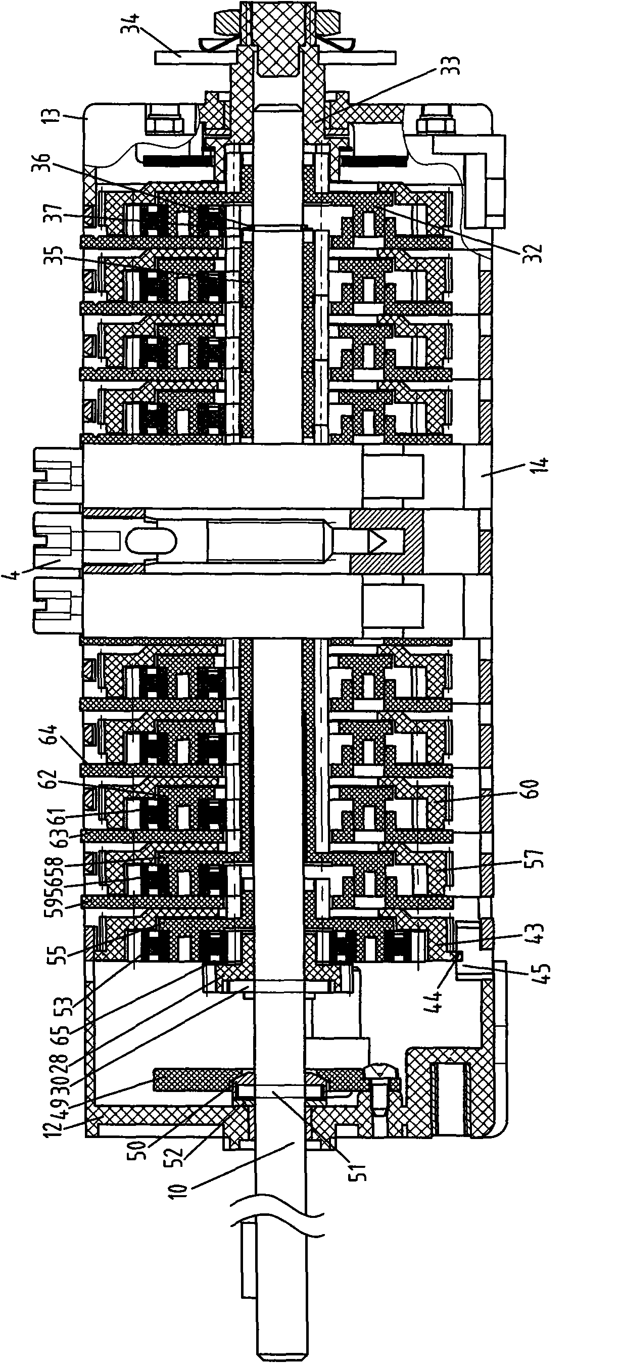
[0042] Such as figure 1 As shown, the cam limit switch includes a housing, several cams 2 and micro switches 3 arranged in the housing. The side of the cam 2 is provided with a transmission gear assembly, and the periphery of the cam 2 and the transmission gear assembly is provided with a guide frame. 1. The transmission gear assembly and the cam pass through the transmission shaft 10, and one side of the guide frame is provided with a worm 4 that can adjust the position of the cam. Described guide frame is made up of head guide frame 12, tail guide frame 13 and several intermediate guide frames 14 that are arranged between them. The micro switch 3 is arranged on the guide frame, and the switch contact pin extends into the gap between the middle guide frames 14 . The housing is composed of a first housing 9, a tail housing 6 and several middle housings 8 arranged between them, and a sealing ring 7 is arranged between two adjacent housings, and the number of 8 middle housings ...


PUM


Abstract

The invention relates to a cam limit switch, which comprises a shell, a driving wheel component arranged in the shell, a worm wheel adjusting component and a contact switch component, and is characterized in that the driving wheel component comprises a first drive-ratio gear component, a second drive-ratio gear component and a third drive-ratio gear component which use driving shafts, driving wheels, planet gears and rotating cams as structural units; the worm wheel adjusting component comprises a worm, a worm wheel, a planet gear meshed with the worm wheel and a rotating cam driven by the planet gear; and the rotating cam of the driving wheel component and an inching switch of the switch component are in movable contact to connect or disconnect an electrified circuit. The cam limit switch solves the problem that the prior cam limit switch has single drive ratio. The cams drive respective inching switch to perform signal transmission, can perform remote control of high-voltage electrical equipment, and are safe and reliable. The cam limit switch also adjusts the positions of the cams conveniently and is simple to maintain.

Description

technical field [0001] The invention relates to a remote control switch, in particular to a cam limit switch for remote control of high-voltage electrical equipment. Background technique [0002] Cam limit switch is a commonly used mechanical switch. It is usually used when the switch device cannot directly limit the displacement of a specific part but can only control the stroke of the part by measuring its rotation angle. It is widely used in lifting transportation equipment, elevators, stages Equipment and other fields, especially places that are dangerous to the staff, such as deceleration and buffering of bridge cranes or spreaders. The switch drives the micro switch through the rotation of the cam to control the high-voltage electrical equipment through the transmission of weak current signals to achieve the positioning or termination of the equipment. [0003] In the existing cam limit switch, each cam is combined into one body, and the cam group is axially provided ...

Claims


Application Information

Patent Timeline
Patent Type & Authority Applications(China)
IPC IPC(8): H01H3/42
Inventor 郑安康郑浙广
Owner NINGBO WEILONG PORT MASCH CO LTD
Why Eureka
Try Eureka