
Driving force control apparatus for hybrid vehicle

A technology of hybrid electric vehicles and control devices, which is applied in the direction of hybrid electric vehicles, power devices, control devices, etc., can solve the problems of reduced motor torque, reduced generator charging, and reduced responsiveness, and achieves the effect of improving controllability

Inactive Publication Date: 2014-03-05
TOYOTA JIDOSHA KK
View PDF3 Cites 0 Cited by
  • Summary
  • Abstract
  • Description
  • Claims
  • Application Information

AI Technical Summary

Problems solved by technology

[0007] In the above-mentioned hybrid vehicle of Patent Document 1, although the engine torque and the motor torque are distributed based on the driver's requested torque, the traction (idle) control or stability (slip) control that intervenes in the drive wheels When the driving torque is reduced, since the target engine speed is set using the best fuel efficiency working line, the engine speed also decreases with the reduction of the driving torque.
After that, the traction control or stability control of the drive wheels is terminated, and the engine speed is increased in order to increase the running torque. However, there is a problem that the responsiveness is reduced by the amount of inertia, and the actual engine speed is increased to Target engine speed will take longer, less controllable and may lead to worsening of vehicle behavior
Therefore, by reducing the power generation load of the generator by the engine, the engine speed is easy to increase, but since the charge amount of the generator is lowered, the torque of the electric motor is lowered, and as a result, the running torque is not sufficiently increased, such as Figure 5 As shown, it takes a long time for the actual driving torque to rise to the target driving torque

Method used


Image

  • Driving force control apparatus for hybrid vehicle
  • Driving force control apparatus for hybrid vehicle
  • Driving force control apparatus for hybrid vehicle

Examples


Embodiment

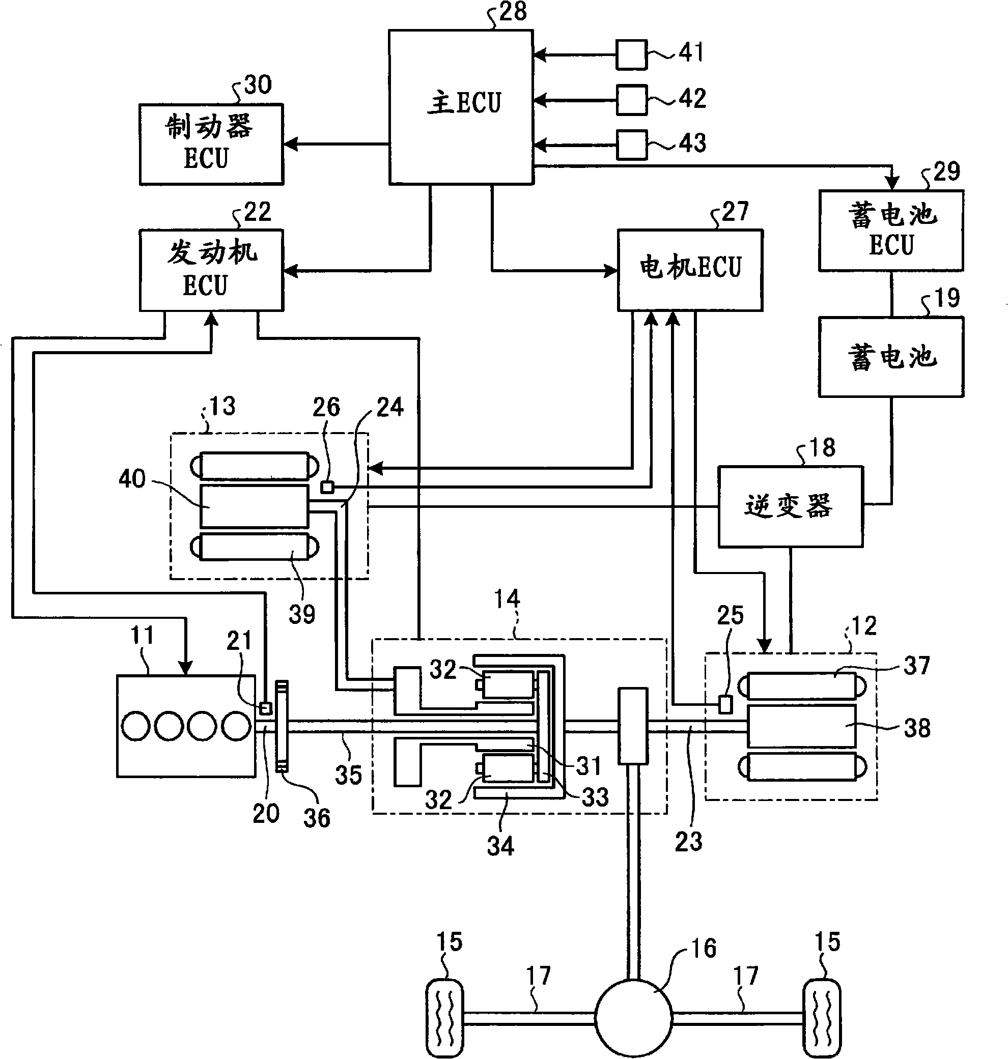
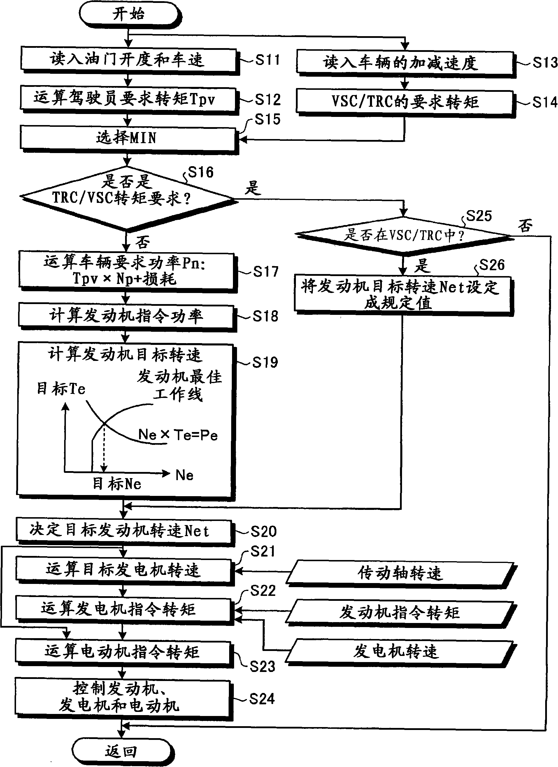
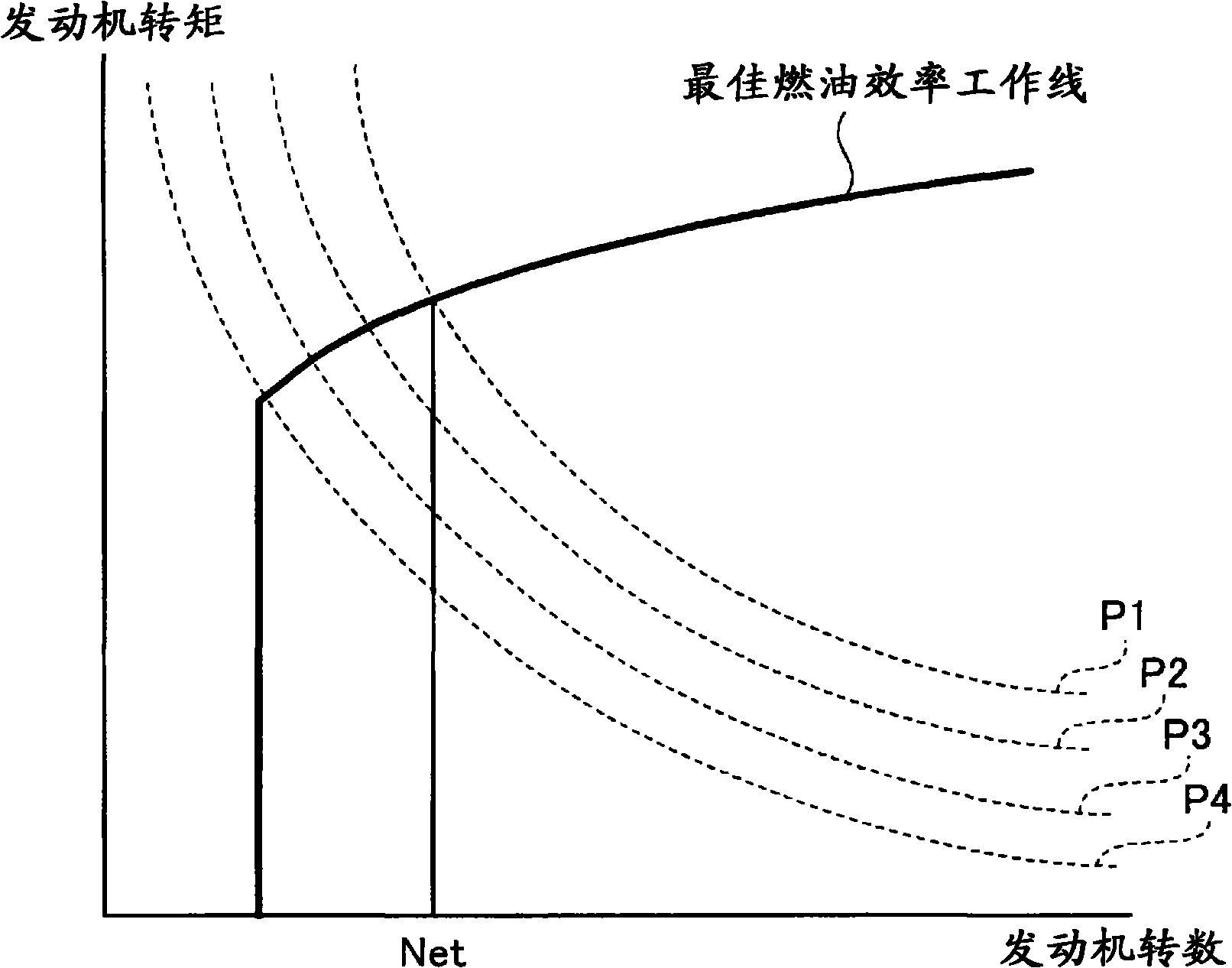
[0025] figure 1 is a schematic configuration diagram of a driving force control device for a hybrid vehicle according to an embodiment of the present invention; figure 2 is a flow chart showing driving force control in the driving force control device for a hybrid vehicle of this embodiment; image 3 is a map for setting the target engine speed in the driving force control device of the hybrid vehicle of this embodiment; Figure 4 It is a graph showing target running torque and actual running torque in the driving force control device for a hybrid vehicle according to the present embodiment.

[0026] In the hybrid vehicle of this embodiment, as figure 1 As shown, an engine 11 and an electric motor (motor generator) 12 are mounted on the vehicle as power sources, and a generator (motor generator) 13 that receives an output from the engine 11 and generates electricity is mounted on the vehicle. These engine 11 , electric motor 12 and generator 13 are connected through a po...


PUM


Abstract

In a driving force control apparatus for a hybrid vehicle, it is configured that an engine ECU (22) can set a target engine rotational number by using a fuel consumption optimal operation-line based on an operating state of the hybrid vehicle, a main ECU (28) can set target output torque of an engine (11) and an electric motor (12) based on the operating state of the hybrid vehicle and the target engine rotational number, and the engine ECU (22) and a motor ECU (27) can control the engine (11) and the electric motor (12) based on the target engine rotational number and the target output torque, and when there is a torque down command in the main ECU (28), the engine ECU (22) sets the target engine rotational number to be higher than the target engine rotational number set by using the fuel consumption optimal operation-line, thereby improving followability of torque up control after torque down control to improve controllability.

Description

technical field [0001] The present invention relates to a drive force control device for a hybrid vehicle capable of running using an engine and an electric motor as power sources. Background technique [0002] In recent years, hybrid vehicles equipped with an engine that outputs torque by fuel combustion and an electric motor that outputs torque by electric power supply and that can run by transmitting the torque of the engine and the electric motor to wheels have been proposed. In such a hybrid vehicle, by controlling the driving and stopping of the engine and the electric motor according to the operating state, the wheels are driven only by the torque of the electric motor, or the wheels are driven by the torque of both the engine and the electric motor. The stored electric power is used for driving, and when the energy of the battery is lowered, the engine is driven to charge the battery. [0003] That is, in a hybrid vehicle, an engine and an electric motor are provide...

Claims


Application Information

Patent Timeline
Patent Type & Authority Patents(China)
IPC IPC(8): B60W10/06B60K6/445B60L11/14B60W10/08B60W20/00F02D29/02B60L50/16
CPCF02D29/02Y02T10/6286B60W2710/0644Y02T10/6239B60W10/08B60W10/06B60W30/18172B60K6/445B60W20/00B60L3/108B60L7/14B60L15/20B60L15/2009B60L2240/12B60L2240/14B60L2240/421B60L2240/423B60L2240/441B60L2240/443B60L2240/64B60L2250/26B60L2260/26Y02T90/16Y02T10/72B60L50/61B60L50/16Y02T10/62Y02T10/64Y02T10/7072Y02T10/70B60W20/10B60W2510/0638B60W2510/081
Inventor 入江喜朗
Owner TOYOTA JIDOSHA KK
Learn More