Tower diameter reducing structure and bubble tower with same

A technology of bubble tower and tower diameter, which is applied in chemical methods for reacting liquid and gaseous medium, chemical/physical/physicochemical fixed reactors, chemical instruments and methods, etc., which can solve the problem that liquid phase backmixing cannot be prevented and other problems, to achieve the effect of sufficient gas-liquid mixing and reliable operation

Inactive Publication Date: 2009-12-23
EAST CHINA UNIV OF SCI & TECH
View PDF2 Cites 4 Cited by
  • Summary
  • Abstract
  • Description
  • Claims
  • Application Information

AI Technical Summary

Problems solved by technology

Therefore, this structure still cannot preve

Method used


Image

  • Tower diameter reducing structure and bubble tower with same
  • Tower diameter reducing structure and bubble tower with same
  • Tower diameter reducing structure and bubble tower with same

Examples


Embodiment 2

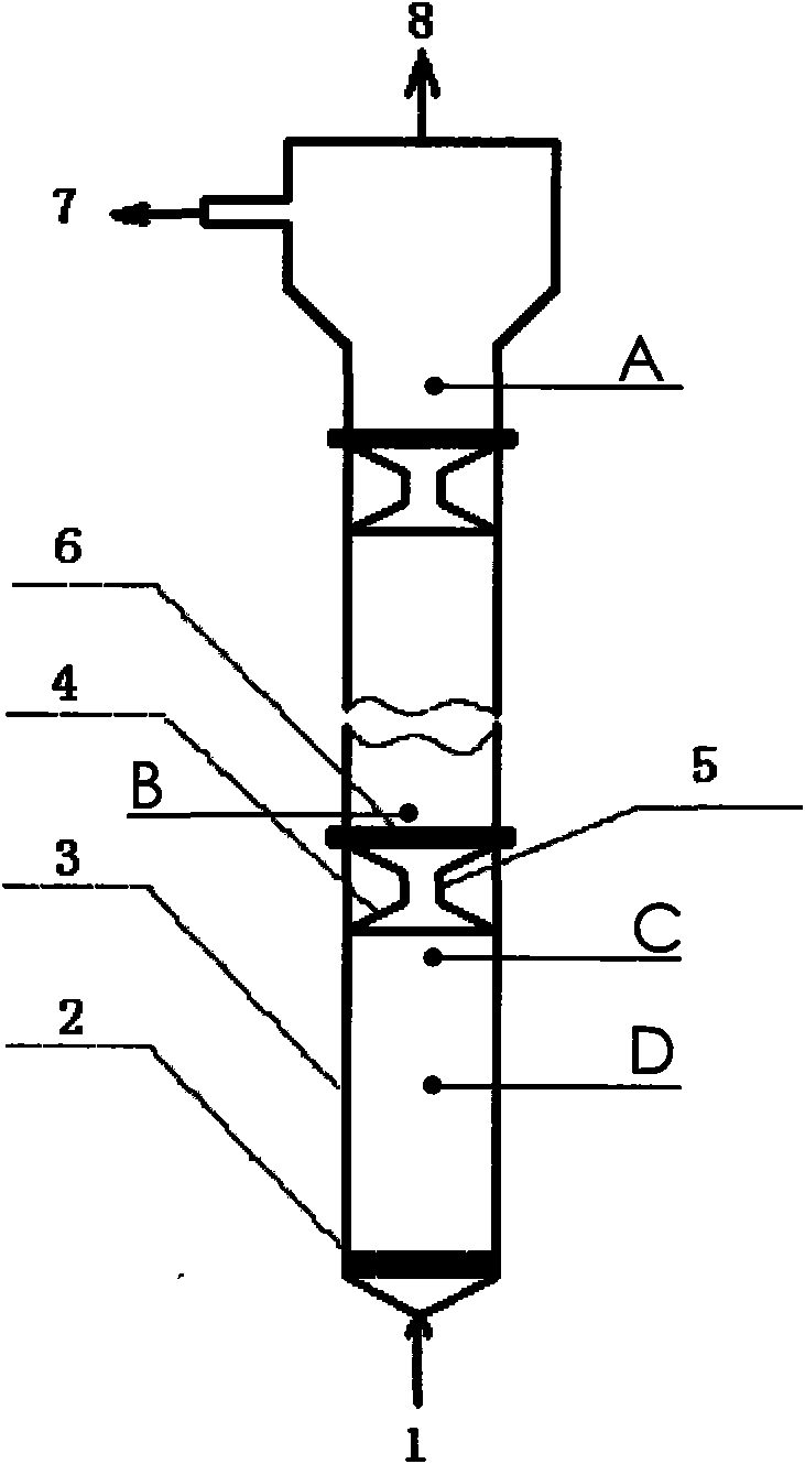
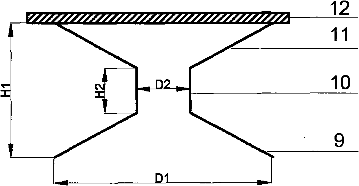
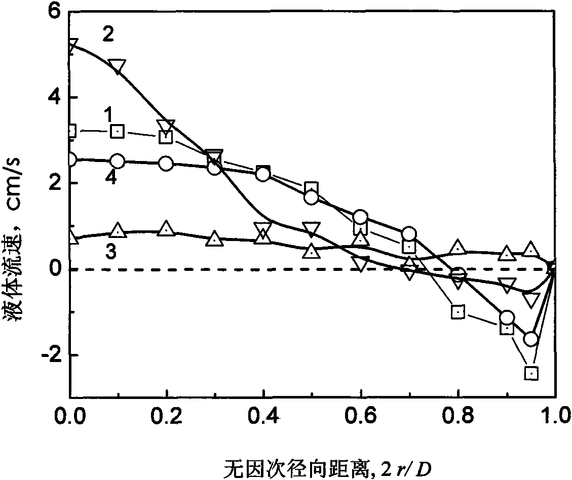
[0047] The liquid velocity distribution measurement result of each point in embodiment 2 is as Figure 4 shown. It can be seen that although the shrinkage values ​​of the tower diameter in these two cases are 12cm and 23cm respectively, the velocity distribution of curve 3 at point C is very similar, indicating that the liquid moves upward with the plunger flow when the tower diameter shrinks. The difference lies in the velocity profile of curve 2 at point B. In Example 1, except that the fluid in the central area flows upwards in the form of a jet, the liquid velocity in other areas is almost 0; but in Example 2, except that the fluid in the central area is the same as in Example 1, the liquid near the wall has a relatively small A large flow rate in the opposite direction will cause back-mixing problems.

[0048] (2) Liquid phase back mixing


PUM


Abstract

The invention relates to a tower diameter reducing structure and a bubble tower with the same. According to the measuring result of liquid velocity distribution and stopping time distribution, the bubble tower provided with 4 diameter reducing parts with internal diameter of 12 cm can lower the back mixing degree by 60 percent, while the bubble tower provided with 4 diameter reducing parts with internal diameter of 23 cm can only lower the back mixing degree by 20-30 percent. The invention effectively overcomes the phenomenon of the liquid back mixing in the bubble tower without installing an internal part for interfering the flow of the liquid in the tower, ensures sufficient air-liquid mixing while lowering the back mixing of the whole tower, has the characteristic of reliable operation and is suitable for various reaction systems such as an air-liquid reaction system and an air-liquid-solid reaction system.

Description

technical field [0001] The present invention relates to a bubble column reactor, especially a bubble column with a diameter-shrinking structure. Background technique [0002] The liquid in the bubble reactor is a continuous phase, and the gas and solid are dispersed phases. It has the advantages of no moving parts, simple structure, large heat capacity, good heat transfer performance, easy temperature control and high safety. However, when the superficial gas velocity is above 5 cm / s, as the small bubbles continuously merge into large bubbles and the large bubbles continue to break up, the flow pattern of the reactor changes from a uniform bubbling flow to a turbulent flow zone, and the gas gathers toward the center of the tower, so the center of the tower appears In the low-density area, the liquid in the tower has a parabolic velocity distribution, that is, the liquid in the center of the tower flows upwards, and the near-wall area flows downwards, resulting in the circula...

Claims


Application Information

Patent Timeline
IPC IPC(8): B01J19/24B01J10/00B01J8/00
Inventor 程振民黄子宾吴阳
Owner EAST CHINA UNIV OF SCI & TECH
Why Eureka
Try Eureka