Integral type stopper capable of controlling inflow gas

An integral, stopper technology, applied in the direction of manufacturing tools, casting melt containers, metal processing equipment, etc., can solve the problems of increasing leakage points, harsh raw materials and precision, and non-concentration, so as to reduce parts and reduce costs Effect

Active Publication Date: 2011-05-25
SINOREF INTERNATIONAL (YIXING) CO LTD
View PDF1 Cites 0 Cited by
  • Summary
  • Abstract
  • Description
  • Claims
  • Application Information

AI Technical Summary

Problems solved by technology

[0005] However, the above-mentioned stopper rod has a complex structure, and the rod of the stopper rod calibration device is separated from the stopper rod body, and must be inserted into the stopper rod body at the end of the stopper rod manufacturing process, and must be used with a sealing member, which increases the Possible leakage points, the production and processing of this kind of rod are very demanding on raw materials and precision, not only the cost is high, but also the processing hours are increased; in addition, the seal is very easy to age and crack under high temperature conditions, which directly affects the rod and stopper body The sealing performance between them not only increases the production cost, but also makes the service life not effectively guaranteed
Although the rods mentioned in the above patents can be replaced and adjusted according to different stopper rod bodies, they often cannot effectively meet the indicators of stability and reliability. When the gas is discharged from the gas outlet, it is very scattered and not concentrated
The pouring port in the lower part is easy to block due to the accumulation of alumina. At the same time, the disadvantage of this structure is that impurities enter during the inflow of gas, which easily blocks the gas outlet, which is difficult to meet the needs of actual use.

Method used


Image

  • Integral type stopper capable of controlling inflow gas
  • Integral type stopper capable of controlling inflow gas
  • Integral type stopper capable of controlling inflow gas

Examples


Embodiment

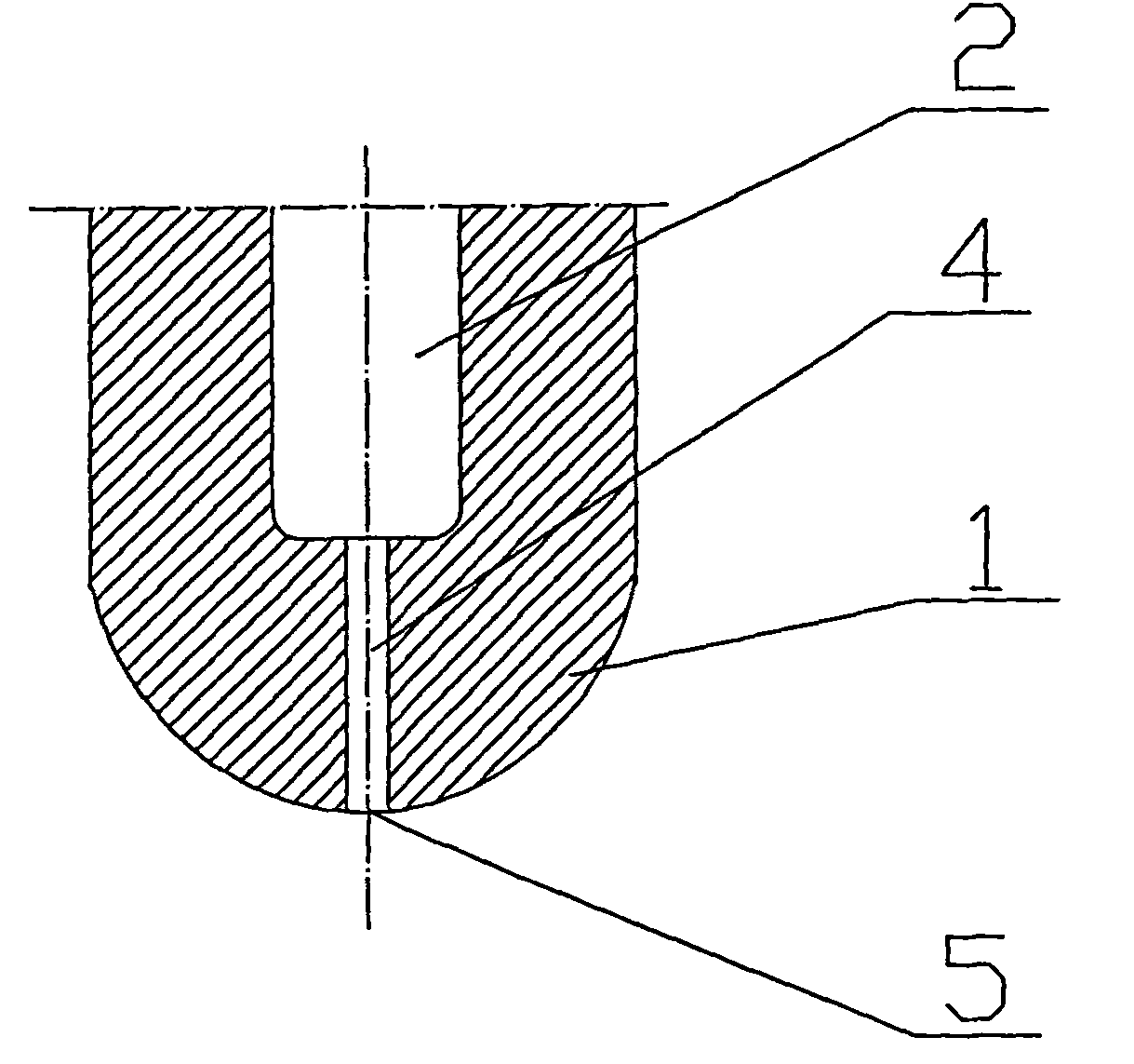
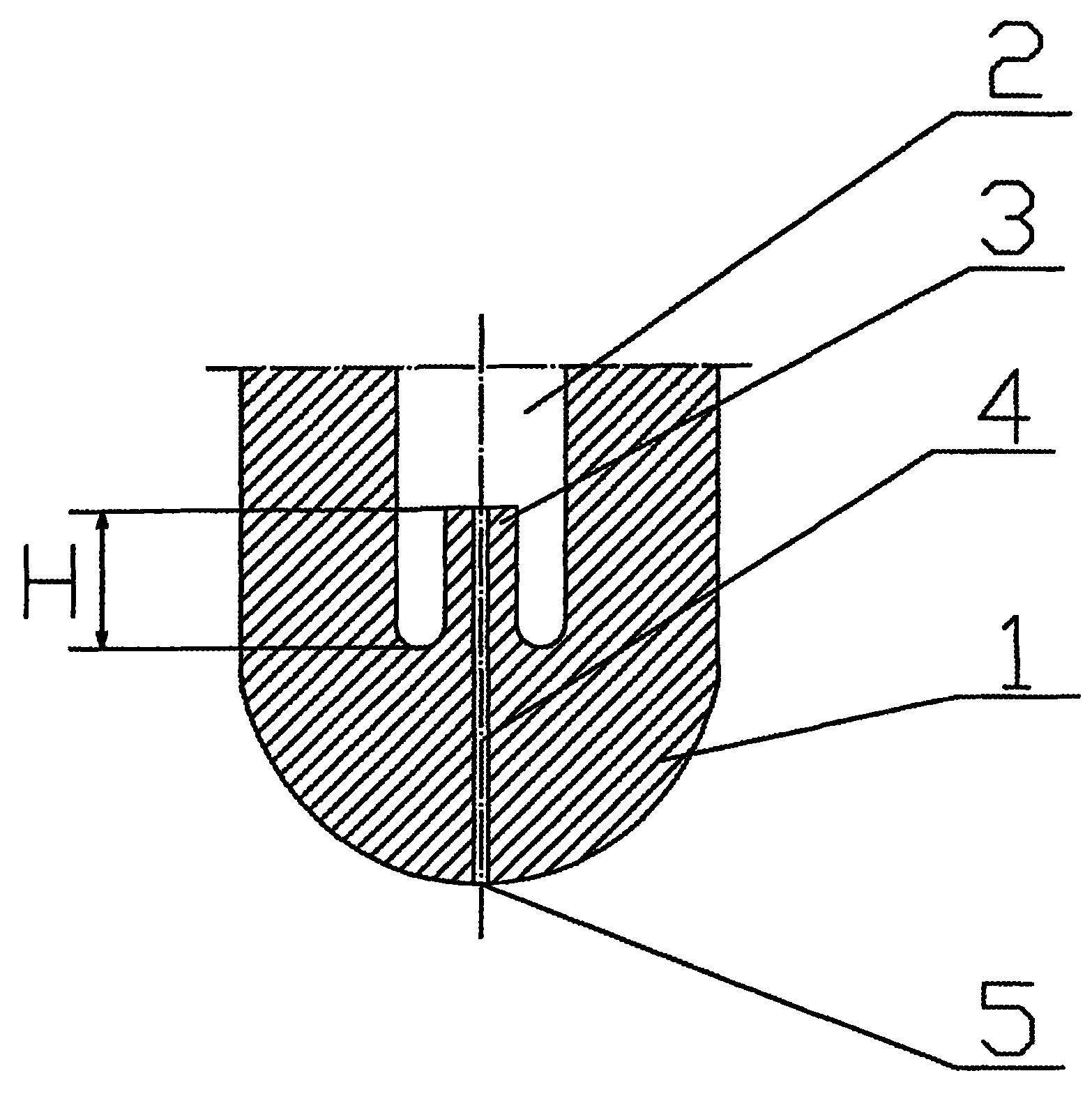
[0023] An integral stopper rod capable of controlling the inflow of gas, comprising a stopper rod body 1, an internal chamber 2 located in the stopper rod body 1, a gas discharge port 5 located at the end of the stopper rod body 1, the internal chamber 2 and the gas discharge port 5 is connected through the gas passage 4. The inner chamber 2 is located at one end of the gas passage 4 and is provided with a gas inlet column 3 extending upward and higher than the bottom of the inner chamber 2. The gas passage 4 extends upward to the top opening of the gas inlet column 3. And communicate with the inner chamber 2; an annular cavity is formed between the outer wall of the gas inlet column 3 and the inner wall of the inner chamber 2; the gas inlet column 3 and the stopper rod body 1 are integral.

[0024] The gas channel 4 is a tubular channel of equal diameter or a tapered channel of unequal diameter or a stepped channel of unequal diameter from the top opening of the gas inlet colu...


PUM

PropertyMeasurementUnit
diameteraaaaaaaaaa

Abstract

The invention relates to an integral type stopper capable of controlling inflow gas, comprising a stopper body, an inner cavity and a gas exhaust port, wherein the inner cavity is positioned in the stopper body, the gas exhaust port is positioned on the tail end of the stopper body, and the inner cavity and the gas exhaust port are communicated and connected by a gas passage. The integral type stopper is characterized in that one end in the inner cavity positioned on the gas passage is provided with a gas inlet column which upwards extends and is over the bottom end of the inner cavity, and the gas passage upwards extends to an opening on the top end of the gas inlet column and is communicated with the inner cavity; an annular hollow cavity is formed between the outer wall of the gas inlet column and the inner wall of the inner cavity; and the gas inlet column and the stopper body form a whole body. In the invention, the gas inlet column fully protrudes above the bottom end of the inner cavity at an inlet of the passage so as to prevent particles and dust from entering the inlet of the passage, is formed by integral pressing in a mould when the stopper is formed, and has good integrity, abrasion resistance of materials, low air permeability and good hot vibration property.

Description

technical field [0001] The present invention relates to a device for controlling the flow of molten material from a vessel through a submerged nozzle, and more particularly to a refractory one-piece stopper rod for controlling the inflow of gas. Background technique [0002] At present, the stopper rod is a slender hollow column structure with a round or conical stopper head at the bottom end, which is suitable for insertion into the throat of the corresponding discharge nozzle, and the stopper rod includes a connecting device of a certain shape at the upper end, so that Control the flow by securing the stopper rod to the external raised structure. Stopper rods are widely used to control the discharge of molten metal from the container installed in the molten liquid, such as controlling the discharge of molten metal from the sprue at the bottom of the ladle or tundish, and are often used to pass steel through the opening at the bottom of the tundish. The sprue and refractor...

Claims


Application Information

Patent Timeline
Patent Type & Authority Patents(China)
IPC IPC(8): B22D41/18
Inventor 徐叶君张兰银王志中
Owner SINOREF INTERNATIONAL (YIXING) CO LTD
Why Eureka
Try Eureka