Minitype stepper adjustable attenuator

A step-by-step attenuator technology, applied in impedance networks, electrical components, multi-terminal pair networks, etc., can solve the problems that the attenuation value cannot be directly displayed, the internal carbon diaphragm is easy to wear, and the attenuation value cannot be found. To achieve the effect of novel structure, complete functions and reduced volume

Active Publication Date: 2011-03-16
SHANGHAI QIANJIN ELECTRONICS EQUIP +1
View PDF0 Cites 0 Cited by
  • Summary
  • Abstract
  • Description
  • Claims
  • Application Information

AI Technical Summary

Problems solved by technology

[0003] Fixed attenuators have the advantages of clear and intuitive attenuation values ​​and stable values, but an attenuator can only have one definite attenuation value. If it wants to cover all commonly used attenuation values ​​(such as 0-15db), there must be 16 different values. Attenuator, which causes inconvenience in production. Sometimes the required attenuation value cannot be found because there are not enough spare parts when the equipment is debugged on site. This is the shortcoming of the fixed attenuator.
[0004] The adjustable attenuator has the advantage of continuously adjusting the attenuation value, but the attenuation value cannot be directly displayed, and the required value must be obtained through calculation with the help of an instrument, and its internal carbon diaphragm is easy to wear after frequent rotation, which may cause The value is unstable, which is the disadvantage of the adjustable attenuator

Method used


Image

  • Minitype stepper adjustable attenuator
  • Minitype stepper adjustable attenuator
  • Minitype stepper adjustable attenuator

Examples


Embodiment Construction

[0031] In order to make the technical means, creative features, goals and effects achieved by the present invention easy to understand, the present invention will be further described below in conjunction with specific illustrations.

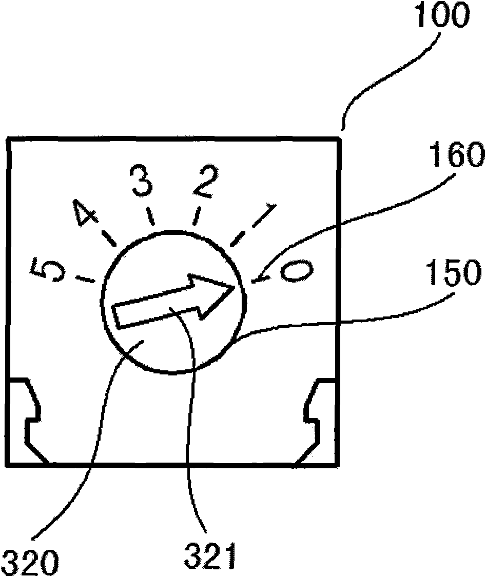
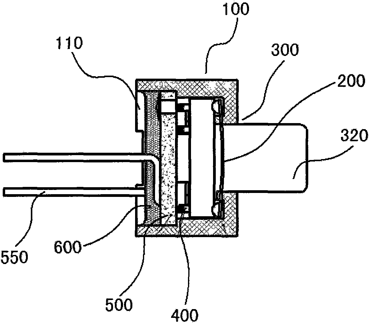
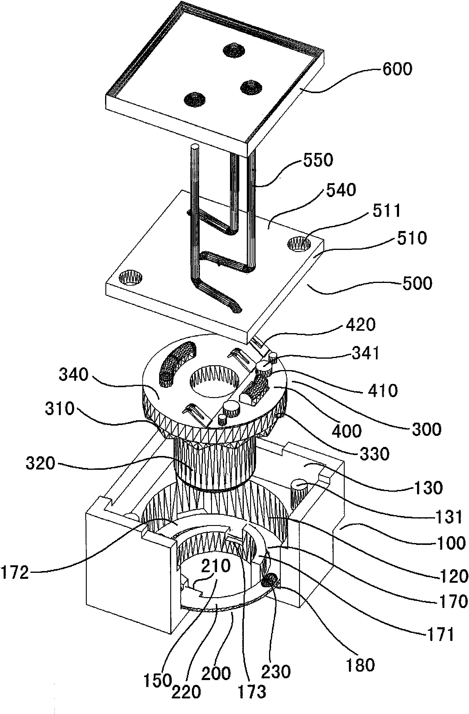
[0032] see Figure 1 to Figure 4 , the micro-step adjustable attenuator of the present invention includes a housing 100 , a positioning reed 200 , a dial 300 , a contact reed 400 , and a substrate assembly 500 . From the perspective of customary operation, the bottom of the housing 100 is not closed, that is to say, there is an installation opening 110, which is a process hole. An accommodating cavity is provided inside the housing 100, and the accommodating cavity is divided into a first accommodating cavity 120 and a second accommodating cavity 130 arranged up and down, wherein the first accommodating cavity 120 is a circular cavity for The circular dial 300 is accommodated, and the second accommodating cavity 130 is a square for accommodatin...


PUM


Abstract

The invention relates to a minitype stepping adjustable attenuator comprising a casing, a positioning spring plate, a driveplate, a contact spring plate and a substrate combination, wherein the positioning spring plate, the driveplate, the contact spring plate and the substrate combination are packaged in the containing cavity of the casing; and three leading-out ends on the substrate combinationare extended out of a packaged part. Three groups of contact pins of the contact spring plate fixed on the driveplate respectively contact with printing contact groups on a substrate through the positioning spring plate blocked in a base casing and a mechanical structure device matched with a stepping gear on the driveplate; moreover, the invention achieves the quantitatively stepping outputting effect of attenuation by rotating the constant angle of the driveplate. In addition, the invention transfers a stop bump to the root of a rotating shaft part on the driveplate to shrink the size; and the invention controls the mechanical rotating angle of the driveplate by the stop bump and a stop ring arranged in the casing.

Description

technical field [0001] The invention relates to a passive attenuator, in particular to a micro-step adjustable attenuator. Background technique [0002] At present, the commonly used passive attenuators can generally be divided into two types, one is a fixed attenuator, and the other is a variable attenuator. The reason why passive attenuators are widely and widely used is that compared with active attenuators (active attenuators usually use PIN tubes or ICs), they have low insertion loss, good impedance matching, simple operation, and no external The hardware control circuit or software control program is easier to replace, there is no nonlinear distortion when the signal is large, and the price is lower. [0003] Fixed attenuators have the advantages of clear and intuitive attenuation values ​​and stable values, but an attenuator can only have one definite attenuation value. If it wants to cover all commonly used attenuation values ​​(such as 0-15db), there must be 16 dif...

Claims


Application Information

Patent Timeline
Patent Type & Authority Patents(China)
IPC IPC(8): H03H7/24
Inventor 汪广海
Owner SHANGHAI QIANJIN ELECTRONICS EQUIP
Why Eureka
Try Eureka