Centrifugal pump with free flow wheel

A centrifugal pump and working wheel technology, applied in the field of centrifugal pumps, can solve the problems of high processing costs, achieve the effect of preventing pump failure and improving durability

Active Publication Date: 2009-12-30
KSB AG
View PDF5 Cites 0 Cited by
  • Summary
  • Abstract
  • Description
  • Claims
  • Application Information

AI Technical Summary

Problems solved by technology

Due to its special shape and its extension from the pump inlet to the pum

Method used


Image

  • Centrifugal pump with free flow wheel
  • Centrifugal pump with free flow wheel
  • Centrifugal pump with free flow wheel

Examples


Embodiment Construction

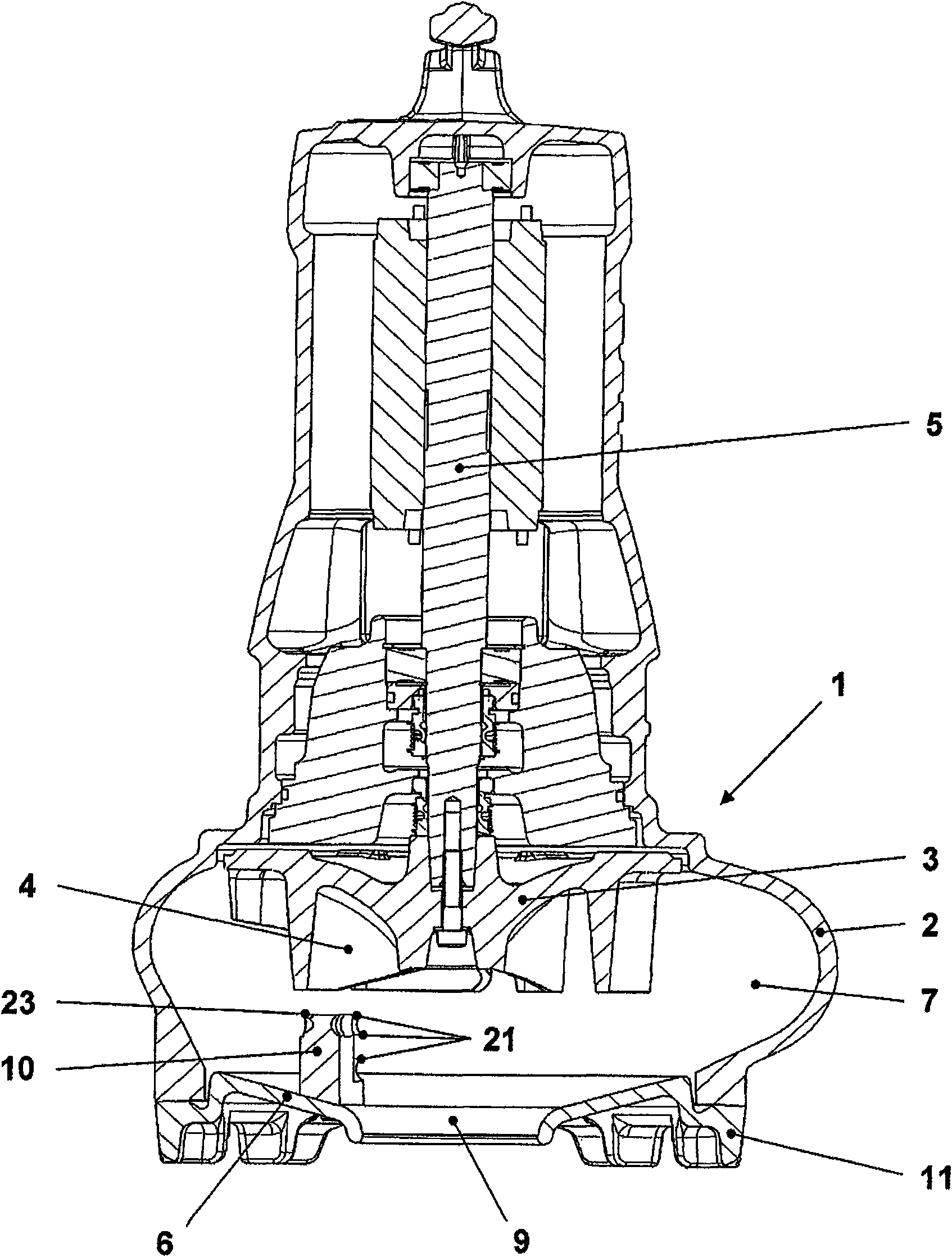
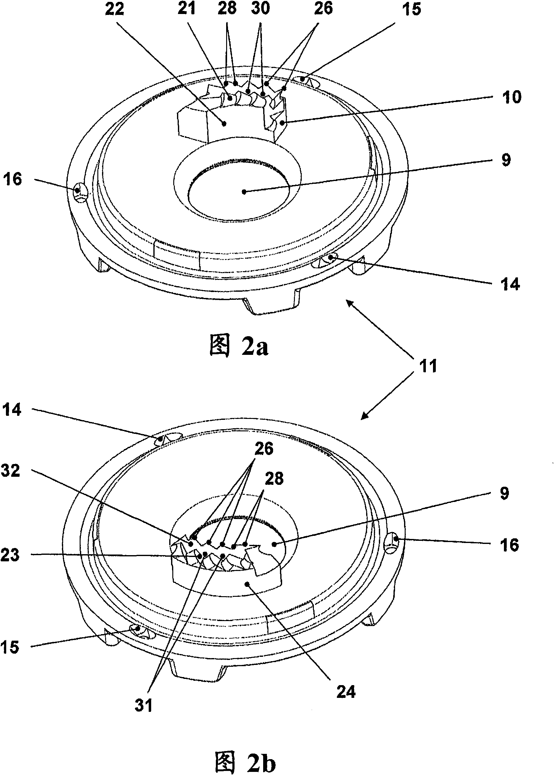
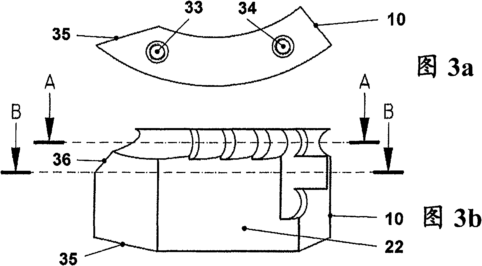
[0022] figure 1 A centrifugal pump 1 is shown for conveying conveying liquids mixed with conveying components which tend to form sticks. The centrifugal pump 1 has a non-clogging impeller 3 arranged rotatably in a housing 2 , which has impeller blades 4 , which is connected to a drive shaft 5 . A vane-free space 7 is arranged between the suction-side housing wall 6 and the unclogged impeller 3 . The centrifugal pump 1 can be connected to the line by means of a pressure connection (not shown). The delivery liquid flows to the pump through the suction hole 9 and a suction line (not shown) can also be connected to this suction hole. A fluid-influencing device 10 is arranged on the suction-side housing wall 6 opposite the impeller blades 4 . Here, in this exemplary embodiment, the predominant part of the suction-side housing wall 6 is formed by a removable suction-side housing cover 11 , where the fluid-influencing device 10 is formed in one piece with the The housing cover is...


PUM


Abstract

The invention relates to a centrifugal pump with a free flow operating wheel, more particularly to a centrifugal pump with a free flow operating wheel rotatably arranged in a casing, wherein, a vane-free space is arranged between the wall of the casing at the pumping side and the free flow operating wheel. The centrifugal pump is equipped with a device for avoiding interrupting fluids, wherein, at least one integrated or split-type fluid-impacting device which protrudes into the vane-free space is arranged at the wall of the casing at the pumping side. The fluid-impacting device (10) is equipped with at least one tear-up device (21, 23).

Description

technical field [0001] The invention relates to a centrifugal pump with a non-clogging impeller (Freistromlaufrad, sometimes called a free-flow impeller) arranged rotatably in a housing, wherein between the suction-side housing wall and the non-clogging impeller A vane-free space is arranged between them and the centrifugal pump is equipped with a device for avoiding flow interruptions, wherein at least one one-piece or multi-piece flow-influencing device protruding into the vane-free space is arranged on the suction-side housing wall (Stroemungsbeinflussendes Mittel). Background technique [0002] The risk of clogging of such centrifugal pumps is increased due to the reduction of waste water caused by the general water saving and the continuous accumulation of waste water with components, rags, non-woven materials or the like which tend to form entanglements (Verstopfungsgefahr). Due to the formation of entanglements of solid material, this viscous wastewater leads to a s...

Claims


Application Information

Patent Timeline
IPC IPC(8): F04D1/00F04D7/04F04D29/70
CPCF04D7/045F04D29/688F04D1/00F04D29/2244
Inventor H·布劳恩R·威特泽尔C·贾杰
Owner KSB AG
Why Eureka
Try Eureka