Fin of microchannel parallel-flow heat exchanger

A technology of parallel flow heat exchanger and microchannel, which is applied in heat exchange equipment, lighting and heating equipment, laminated components, etc., can solve problems such as unreasonable structure of tube-fin heat exchanger, and achieve good mechanical properties and high-quality products Easy processing and moderate resistance

Inactive Publication Date: 2009-12-30
ZHEJIANG KANGSHENG CO LTD
View PDF2 Cites 10 Cited by
  • Summary
  • Abstract
  • Description
  • Claims
  • Application Information

AI Technical Summary

Problems solved by technology

[0005] The purpose of the present invention is to solve the problem that the pipe diameter of the heat exchanger is gradually shrinking and the structure of the tube-fin heat exchanger is relatively unreasonable, and to provide a microchannel with a reasonable structure that can effectively improve the heat exchange effect of the heat exchanger Finned with Parallel Flow Heat Exchanger

Method used


Image

  • Fin of microchannel parallel-flow heat exchanger
  • Fin of microchannel parallel-flow heat exchanger
  • Fin of microchannel parallel-flow heat exchanger

Examples


Embodiment Construction

[0023] The technical solutions of the present invention will be further specifically described below through the embodiments and in conjunction with the accompanying drawings.

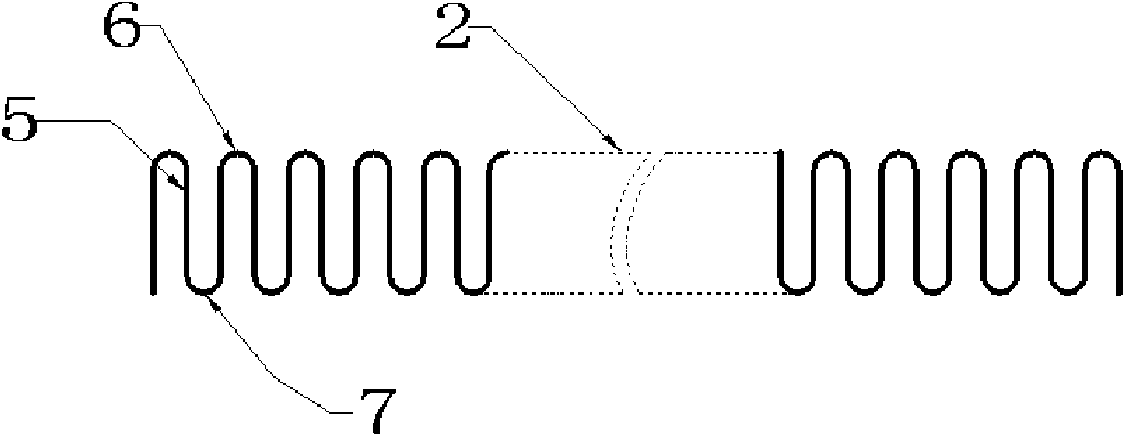
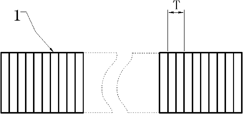
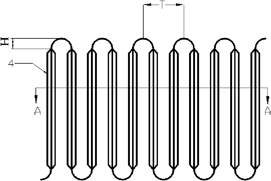
[0024] see Figure 1 to Figure 5 , this embodiment includes fins 1, substrate 2, the substrate 2 is extended and distributed in a sine wave, the wave distance T of the substrate 2 is set to 2.5 mm, and two groups of louvers are set on each substrate side wall 5 of the substrate 2 3. Each group of shutters 3 is tilted along the two sides of the substrate 2 and forms an included angle with the surface of the side wall 5, and the included angle B is 30°. The included angle B between two groups of louvers 3 on the same side wall 5 and the surface of the substrate 2 is symmetrical to each other. The louvers on adjacent side walls overlap each other after being folded along the crests or troughs, and the air flow direction is perpendicular to the extending direction of the substrate 2 .

[0025] Specificall...


PUM


Abstract

The invention relates to the technical field of heat exchangers, in particular to a fin of a microchannel parallel-flow heat exchanger. The fin of a microchannel parallel-flow heat exchanger comprises a fin and a substrate, and is characterized in that: the substrate extends and distributes in a sine wave; each side wall of the sine wave of the substrate is provided with two sets of shutters consisting of a plurality of strips; each set of shutter raises along the surfaces on two sides of the substrate to form included angles with the surfaces of the side wall; included angles formed between the two sets of shutters on the same side wall and the surfaces of the substrate are mutually symmetric; after being folded in the extension direction of the sine wave, the shutters of adjacent side walls are coincide; and the flow direction of an air flow is perpendicular to the extension direction of the substrate. The fin of the microchannel parallel-flow heat exchanger has the advantages of ensuring proper resistance to air flow flowing in the fin, achieving optimal air flow, effective heat exchange area and heat exchange efficiency, along with easy manufacture, low cost and excellent mechanical performance.

Description

technical field [0001] The invention relates to the technical field of heat exchangers, in particular to fins of parallel flow heat exchangers for microchannels. Background technique [0002] The heat exchanger is a common main component in the heating and cooling industry. Its structure and quality are directly related to the effect of the overall product. The technical requirements for the high efficiency and energy saving performance of the heat exchanger are getting higher and higher. Air conditioners, refrigerators and freezers, especially the tube-fin heat exchangers used in air conditioners are gradually reduced in diameter, such as reducing from the original 9.53mm to the current small diameter of 5mm, and the fins have also been optimized. Fins with high heat transfer coefficient to improve heat transfer efficiency. However, due to the inherent disadvantages of the tube-fin heat exchanger, the heat transfer between the fin and the round tube is through tight contac...

Claims


Application Information

Patent Timeline
Patent Type & Authority Applications(China)
IPC IPC(8): F28F3/04
Inventor 陈汉康成守权闫志恒许显钧
Owner ZHEJIANG KANGSHENG CO LTD
Why Eureka
Try Eureka