Mesh for Screening a User from Direct Impact of a High Pressure Fluid by Diffusing the Fluid Stream

a high-pressure fluid and mesh technology, applied in mechanical equipment, maintenance and safety accessories, transportation and packaging, etc., can solve the problem that the sleeves/stocking materials can easily ruptur

Inactive Publication Date: 2016-09-15
PIGGOTT ANDREW
View PDF0 Cites 0 Cited by
  • Summary
  • Abstract
  • Description
  • Claims
  • Application Information

AI Technical Summary

Benefits of technology

[0012]It has been discovered that if a high pressure fluid (such as a hydraulic fluid at 5000 psi or greater) is attempted to be restrained at or by a woven sleeve or stocking that surrounds a hose, pipe or tube that carries the high pressure fluid, the sleeve / stocking material can readily rupture, whereby a pinhole jet of fluid can still issue from the hose, pipe or tube.
[0014]Thus, the death from pinhole fluid injection into a user can be eliminated. Injury from fluid contact can also be eliminated or substantially ameliorated (though in the latter case, provided that protective clothing and eyewear is being worn to protect against diffused fluid).
[0015]In one form the mesh is formed from metal wire, to provide dimensional stability, environmental resistance and robustness in industrial applications. The mesh is usually woven. Whilst it is conceivable that at some (e.g. lower) fluid pressures that a polymer or other material mesh may be considered, in industrial applications metal meshes are favoured. In one embodiment, for example, in applications where there exists high levels or moisture or corrosive media, the mesh can be formed from stainless steel wire, though other corrosion resistant metals can be employed for the mesh (e.g. such as copper, galvanised steel wire etc).
[0019]The entire panel or edge(s) of the mesh panel can optionally be reinforced for fastening with respect to the frame. This can allow the mesh to be adequately supported at a remote location, and restrained and stabilised for fluid impact, and to resist other inadvertent impacts. For example, the entire panel or at least the edge(s) of the mesh can be reinforced with a polymeric rubber that is attached (e.g. moulded, adhered, cold-rolled etc) thereat. The mesh panel can also be provided with a series of holes (e.g. eyelets) along it edge(s) for enabling its fastening to the frame (e.g. by bolting, tying, staple toggles etc).
[0020]When the entire mesh panel is coated on one or both sides with the polymeric rubber this can provide for maximum mesh protection during ordinary use. Then, at high pressure fluid impact, the rubber coating can simply disintegrate to expose the mesh, with fluid diffusion still occurring as the fluid travels through the mesh. The polymeric rubber can be vulcanised. A particular suitable rubber is vulcanised and calendered styrene butadiene rubber (SBR) because of its high tensile strength, abrasion resistance, and moderate ozone and ageing resistance.
[0028]The mesh can be supported by mounting it to a frame. Such a frame can be arranged at a cage that at least partially surrounds the user in use. In this way, a user can be protected from catastrophic injury whilst working in the vicinity of high pressure fluid lines.

Problems solved by technology

It has been discovered that if a high pressure fluid (such as a hydraulic fluid at 5000 psi or greater) is attempted to be restrained at or by a woven sleeve or stocking that surrounds a hose, pipe or tube that carries the high pressure fluid, the sleeve / stocking material can readily rupture, whereby a pinhole jet of fluid can still issue from the hose, pipe or tube.

Method used


Image

  • Mesh for Screening a User from Direct Impact of a High Pressure Fluid by Diffusing the Fluid Stream
  • Mesh for Screening a User from Direct Impact of a High Pressure Fluid by Diffusing the Fluid Stream
  • Mesh for Screening a User from Direct Impact of a High Pressure Fluid by Diffusing the Fluid Stream

Examples


example 1

[0059]A non-limiting Example of forming a panel as disclosed herein will now be provided.

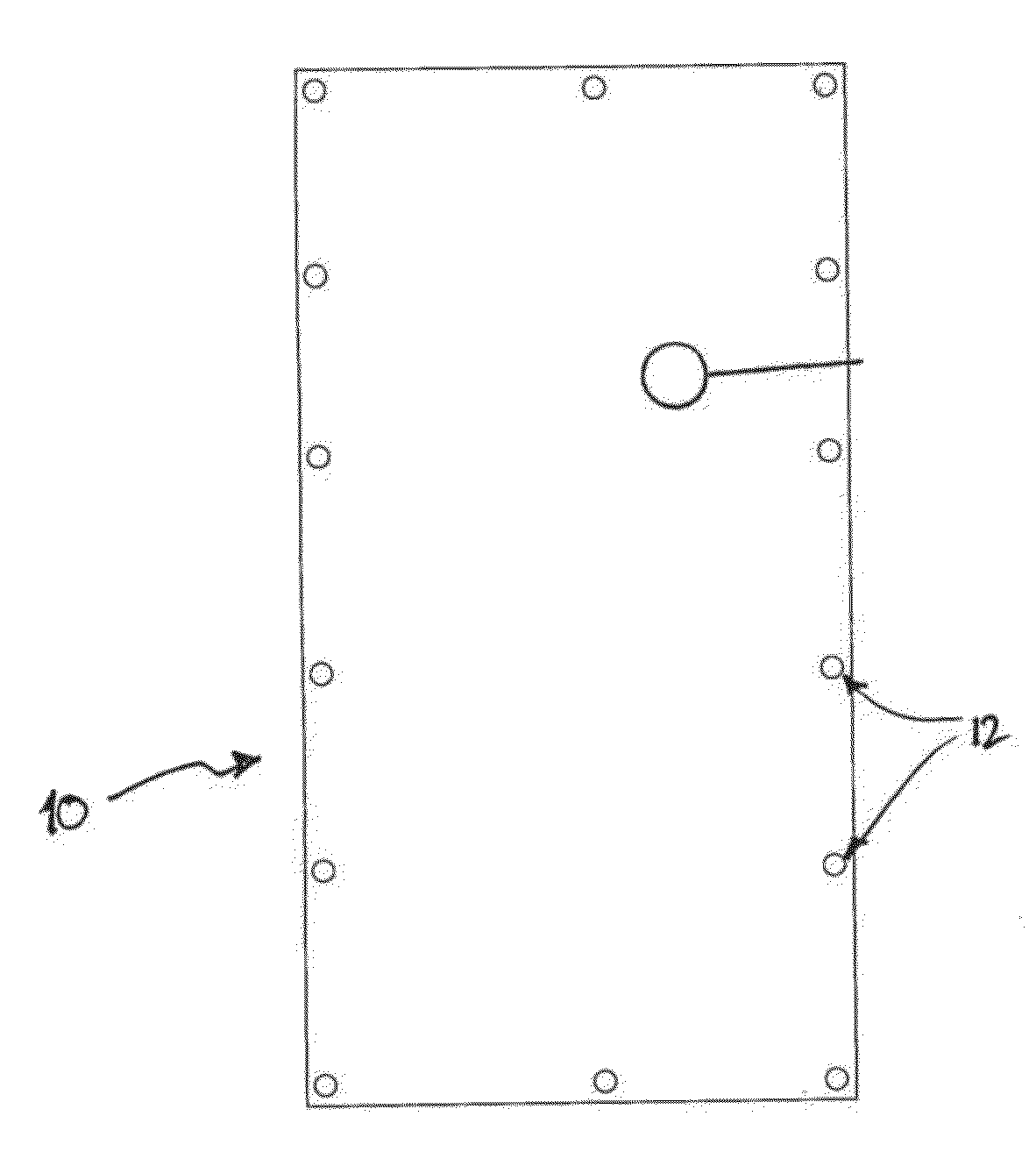
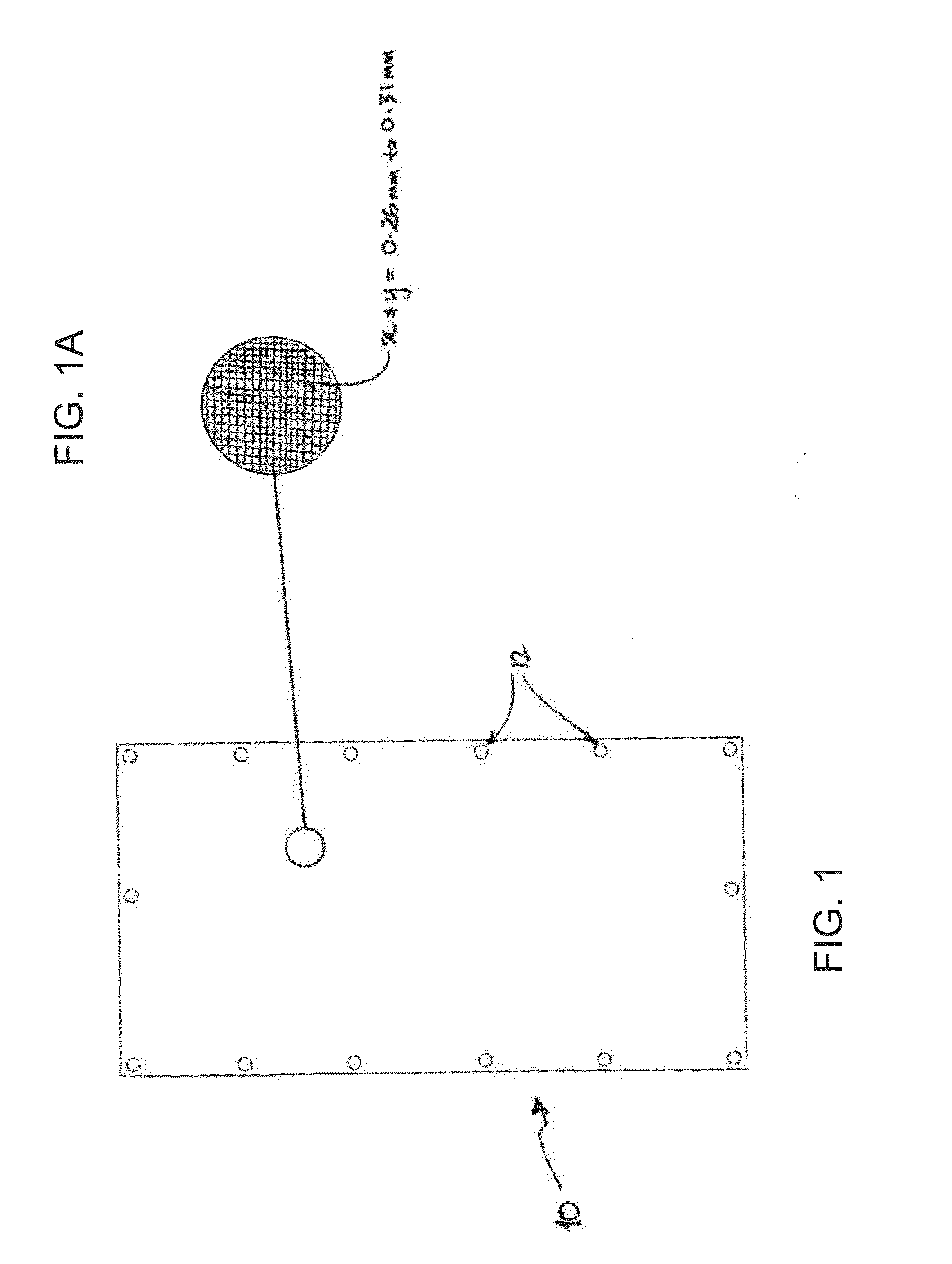
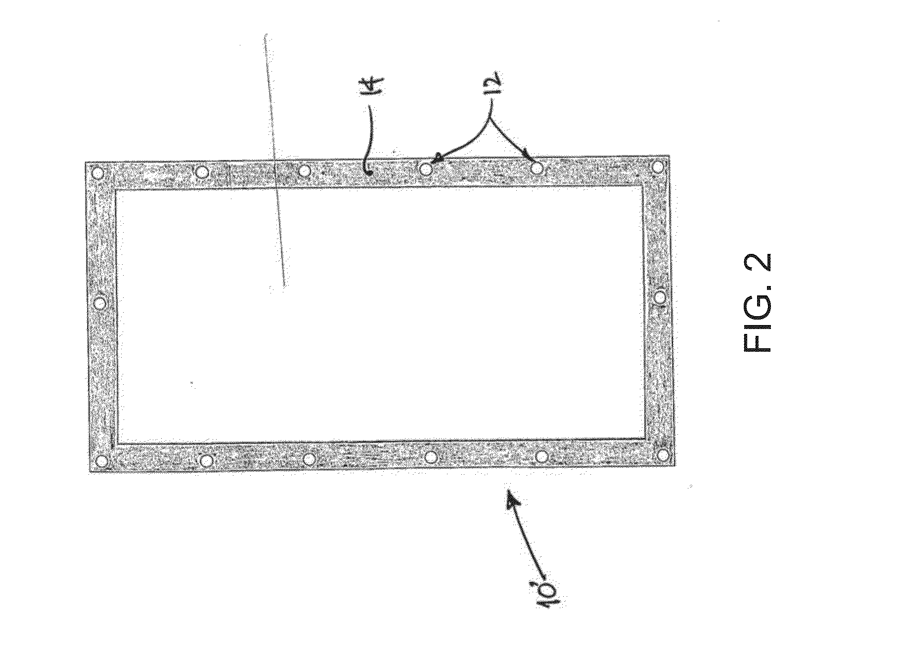
[0060]In the panel forming process a mesh comprising a market grade (316 grade) woven stainless steel mesh was cut to an approximate panel size of 1000 mm×1500 mm. A process of hot vulcanising an SBR rubber sheet of approximately 1.5 mm thickness onto the mesh comprised the following steps:

1. The mesh and the suitably sized SBR rubber sheet were brushed with a cement bonding solution. A suitable bonding solution employed was a “two-pack” rubber cement of Toyo Tyre & Rubber having the manufacturer's code F2444 (UN No. 1287).

2. The solution was allowed to “tact” off (i.e. go tacky).

3. The rubber sheet was applied to one side of mesh.

4. Steps 1-3 were repeated for the other side of the mesh with another suitably sized SBR sheet.

5. The product from 4, was clamped and autoclave cured (at 150° C. and at a pressure 400 kPa). The autoclave curing time was approximately 30 mins.

6. Sections of the resulti...

example 2

[0062]A non-limiting Example of the mesh in use in accordance with the screening method disclosed herein will now be provided.

[0063]Firstly, a mesh for the mesh panel was selected that was suitable for screening against a hydraulic fluid comprising a water-based mixture with mineral oil, (95% water, 5% mineral oil).

[0064]In an underground mining and tunneling trial, it was noted that such a fluid was subjected to high fluid pressures of up to 5000 psi (and sometimes 6000 psi) in fluid lines used to power much of the mining and tunneling equipment. This included fluid lines to the stage loaders, belt headings, roof supports, and cutting machines and shearers. It was observed in a typical longwall mining operation that around 9500 high fluid pressure fluid lines were employed across a longwall of approximately 250 m width and 3 km length. It was further noted that the most common form of fluid line failure was a so-called pinhole failure, whereby an approximately 2 mm pinhole jet ejec...


PUM


Abstract

A mesh for use in screening a user from direct impact of a high pressure fluid J is adapted for receiving and diffusing S the high pressure fluid therethrough when positioned in relation to a location P from which the high pressure fluid issues. The mesh can form part of a screening apparatus that comprises a frame for supporting the mesh in a spaced relationship to the location P from which the high pressure fluid issues. The mesh and apparatus can be employed in a method in which the high pressure fluid is diffused at a first location that is spaced with respect to a second location from which the high pressure fluid issues.

Description

TECHNICAL FIELD[0001]Disclosed is a method and apparatus for the screening of high pressure fluids, especially hydraulic fluids, and especially in mining (e.g. underground) and civil construction, and related applications. However, it should be appreciated that the method and apparatus can readily be adapted for use in the many other applications of high pressure fluids.BACKGROUND ART[0002]Hoses, pipes and tubes that carry high pressure fluids can be prone to rupture, especially when they are required to be formed from a flexible material for a given application. Machinery and tools that are powered by hydraulic fluid (e.g. as employed in underground mining, civil construction and related applications) can be supplied with hydraulic fluid in hoses, lines, etc at pressures of 5000-6000 psi or even greater. Should a hose rupture occur that takes the form of a small so-called “pinhole”, the issuing jet of fluid can have a needle-like profile. Such a fluid jet can function like a lance ...

Claims


Application Information

Patent Timeline
Patent Type & Authority Applications(United States)
IPC IPC(8): F16P1/02B23Q11/08
CPCB23Q11/0891F16P1/02Y10T137/7043
Inventor PIGGOTT, ANDREWWESTON, DAVID LESLIE
Owner PIGGOTT ANDREW
Why Eureka
Try Eureka