
Encoder home position sensing method and system

A starting position and encoder technology, applied in the field of rendering devices, can solve problems such as increasing the cost of the third sensing channel

Inactive Publication Date: 2009-12-30
XEROX CORP
View PDF1 Cites 10 Cited by
  • Summary
  • Abstract
  • Description
  • Claims
  • Application Information

AI Technical Summary

Problems solved by technology

This third channel technology adds the cost of a third sensing channel to the encoder reader and its associated cabling

Method used


Image

  • Encoder home position sensing method and system
  • Encoder home position sensing method and system
  • Encoder home position sensing method and system

Examples


Embodiment Construction

[0028] The specific values ​​and configurations discussed in these non-limiting examples may be varied and are cited for illustration of at least one embodiment only and are not intended to limit the scope of the invention. Note that in Figure 1-5 In , the same or similar modules are generally indicated by the same reference numerals.

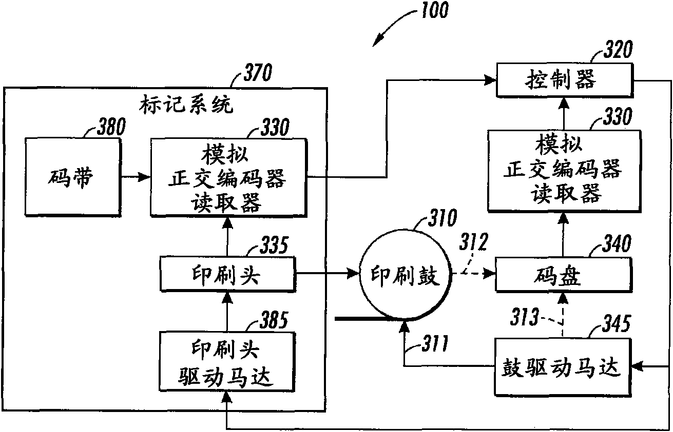
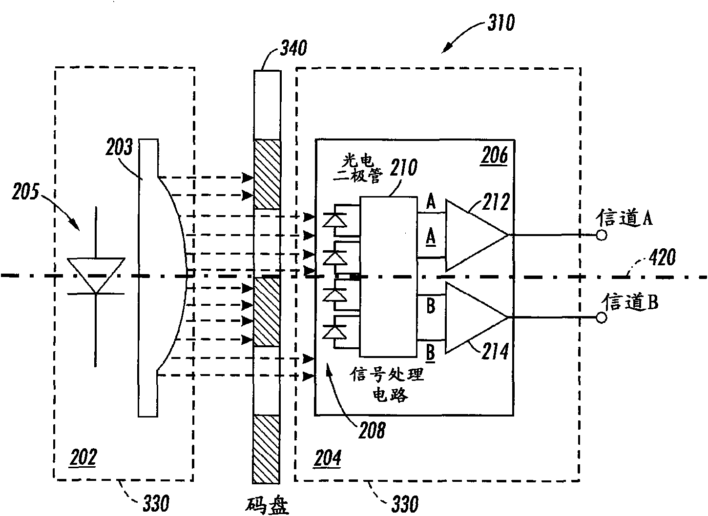
[0029] It will be appreciated that printing device 100 may form part of a rendering device or system, such as a copier, printer, facsimile, or the like. like figure 1 As depicted, marking system 370 may be used to apply marking signals to print drum 310 to form an image that is transferred to a print output medium. Marking system 370 may be, for example, an inkjet marking system or an electrophotographic marking system utilizing an optical encoder system. Printing apparatus 100 typically includes a code device, such as a code wheel 340 , to sense the angular position and velocity of print drum 310 . Printing apparatus 100 may also include ...


PUM


Abstract

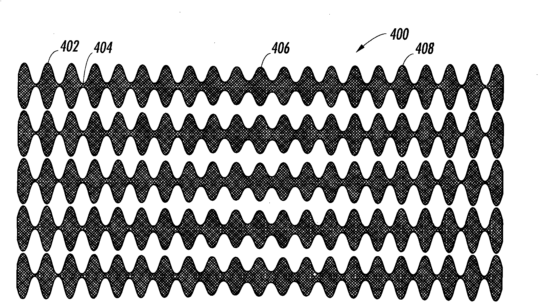
The invention discloses an encoder home position sensing system and a method, comprising an analog quadrature encoder reader and either a code wheel or a code strip. The code wheel is provided with an optical track composed of annular ring patterns, the thickness of which can be modulated by a sinusoidal function about the code wheel circumference, wherein one cycle of a sine wave is corresponding to one encoder cycle. In one region of the optical track the amplitude of the sine function is changed to imbed an absolute reference home position. The region of the optical track can be sensed and used to determine an absolute system position. The linear code strip is similarly constructed with lines along the direction of motion, the thickness of which is modulated with a sine function, wherein one cycle of the sine wave is corresponding to one encoder cycle and the amplitude of the sine wave function is changed to imbed an absolute reference home position in the optical track.

Description

technical field [0001] Embodiments of the invention relate generally to rendering devices and techniques. The invention also relates to incremental position encoders. Embodiments of the invention also relate to methods and systems for sensing encoder home positions. Background technique [0002] Rendering devices - such as printers, copiers, etc. - may use incremental encoders to track the position of moving parts such as print drums, rotating shafts and print heads. The position or angle of these moving parts is usually controlled by a drive mechanism and measured by an encoder. Incremental encoders typically consist of a movable code wheel or code strip with a light track consisting of alternating transparent and opaque Passing between and moving relative to them, the illumination source is usually a light emitting diode (LED) and the photosensitive element is usually a photodiode. [0003] As the codewheel / strip moves, it interrupts the light from the illumination sou...

Claims


Application Information

Patent Timeline
Patent Type & Authority Applications(China)
IPC IPC(8): G01D5/32G01D5/347B41J29/38
CPCG01D5/366G01D5/24409G01D5/3473G01D5/34746G01D5/34707H03M1/06B41J2/44B41J29/393G03G15/607
Inventor D·D·马特森D·L·尼里姆
Owner XEROX CORP
Learn More