Clock-synchronization digital phase-locking method and device

A digital phase-locking and clock synchronization technology, applied in the field of signal phase-locking, can solve the problems of increasing the locking time and reducing the sensitivity of the phase-locked loop, etc., and achieve the effect of fast phase-locking

Inactive Publication Date: 2012-10-03
DONGGUAN UNIV OF TECH
View PDF5 Cites 0 Cited by
  • Summary
  • Abstract
  • Description
  • Claims
  • Application Information

AI Technical Summary

Problems solved by technology

The method of adding no-operation can play a very good role when the phase difference between the reference signal and the feedback signal is not large. When the phase difference between the reference signal and the feedback signal is relatively large, the locking time will be increased.
Moreover, there are a large number of no-operation instructions, which will reduce the sensitivity of the phase-locked loop

Method used


Image

  • Clock-synchronization digital phase-locking method and device
  • Clock-synchronization digital phase-locking method and device
  • Clock-synchronization digital phase-locking method and device

Examples


Embodiment Construction

[0032] The present invention will be further described below with specific embodiments. Use the method and device described in the present invention to lock the falling edge of a signal with a frequency of 8KHz (the frame synchronization signal commonly used in communication systems), and output a T1 clock signal (1.533MHz) synchronized with the falling edge of the reference signal as an example Be explained.

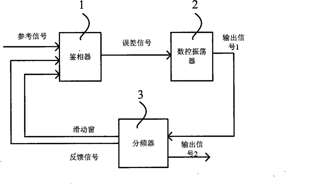
[0033] as attached figure 2 As shown, the digital phase-locked loop includes a phase detector 1, a digitally controlled oscillator 2 and a frequency divider 3. The phase detector 1 is used for phase comparison between the reference signal and the feedback signal, and generates an error signal in different regions of the sliding window according to the edges of the reference signal and the feedback signal. The numerically controlled oscillator 2 generates a corresponding phase-adjusted output signal 1 according to the error signal output by the phase detector 1 of the...


PUM


Abstract

The invention relates to the technical field of phase locking, in particular to a clock-synchronization digital phase-locking method and a device. The method comprises the following steps: firstly, comparing the phases of a reference signal and a feedback signal according to a gliding window; judging that the phase of the feedback signal is a leading phase, a lagging phase or an identical phase relative to the phase of the reference signal; generating an error signal for presenting the three messages; secondly, adjusting the phases of the error signal and the feedback signal and outputting the signals with the adjusted phases as a first output signal; thirdly, processing the first output signal by frequency division, generating the feedback signal, the gliding window for comparing the phases of the reference signal and the feedback signal and the second output signal output to the exterior; and continuing the first step. The technical scheme of the invention occupies less logic units and can rapidly lock up the phases and effectively prevent the feedback signal to approach to the reference signal in a damped oscillation mode.

Description

technical field [0001] The present invention relates to the technical field of signal phase locking, in particular to a clock synchronous digital phase locking method and device. Background technique [0002] In the fields of communication, instrumentation, automatic control, etc., it is often necessary to use signal phase-locking technology to process various input signals. The signal phase-locked loop circuit is a commonly used signal phase-locking technology, such as clock synchronization in data reception. attached figure 1 is a block diagram of an existing digital phase-locked loop, as attached figure 1 As shown, a general digital phase-locked loop includes: a phase detector, which is used to compare the phase difference between the input reference signal and the feedback signal, and outputs an error signal representing the phase difference; low-pass filter, low-pass filter Immediately after the phase detector, it is used to filter out the low-frequency signal in the...

Claims


Application Information

Patent Timeline
Patent Type & Authority Patents(China)
IPC IPC(8): H03L7/06H03L7/085
Inventor 刘华珠黄海云陈雪芳伍方辉赖树明余成
Owner DONGGUAN UNIV OF TECH
Why Eureka
Try Eureka