
Eureka
For R&D, Eureka makes reading and utilizing patents & technical documents easy.
Eureka AIR
Designed for self-driven R&D workflows. Generate viable solutions, solve complex R&D challenges, empower your innovation with AI.

Eureka Materials
Designed for material experts only. Revolutionize your material R&D, from search, analyze, to developing new materials.

TechResearch
Generate reliable direction feasibility study reports for your R&D in just a few steps.

TechSeek
Discover and master advanced knowledge NOW. Basics, ideas, possibilities, all at once.

TechMind
As an expert in R&D Theories, TechMind can generates customized viable solutions instantly.

TechRisk
Analyze your overall solution with one click, know your potential R&D risks in advance.

TechMonitor
Get weekly tech updates, stay abreast of the latest tech innovations and key insights.
Base station, communication terminal, transmission method, and reception method
A technology of base station and channel coding method, applied in the field of wireless communication, can solve the problem of insufficient research and achieve the effect of high-efficiency transmission
- Summary
- Abstract
- Description
- Claims
- Application Information
AI Technical Summary
Problems solved by technology
Method used
Image

Examples
Embodiment 1
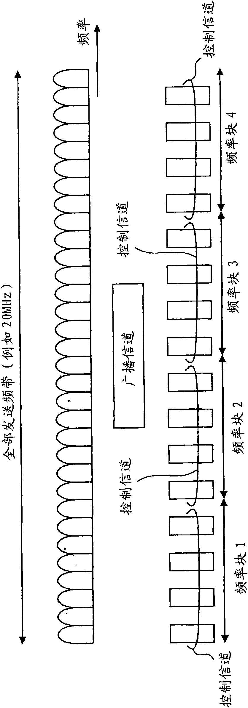
[0094] figure 2 Indicates the frequency band used in one embodiment of the present invention. For convenience of description, specific numerical values are used, but the numerical values are merely examples, and various numerical values may be used. As an example of the frequency band (the entire transmission frequency band) provided to the communication system, there is a bandwidth of 20 MHz. The entire transmission band includes four frequency blocks 1 to 4, and each frequency block includes a plurality of resource blocks including one or more subcarriers. In the illustrated example, a case where a plurality of subcarriers are included in each frequency block is schematically shown. In this embodiment, as the communication bandwidth, four kinds of 5MHz, 10MHz, 15MHz, and 20MHz are prepared in advance, and user equipment (including communication terminals, mobile terminals, fixed terminals, etc.) Any one of the bandwidth to communicate. A terminal communicating wit...
Embodiment 2
[0228] The common control channel (including part 0) is information required by all users. Since the data channel is decoded based on the common control channel, error detection (CRC) coding and channel coding are performed on the common control channel. In the second embodiment of the present invention, specific examples of the error detection coding and channel coding will be described. Figure 4B is a diagram corresponding to a structure in which L1 / L2 control information (part 0) and L1 / L2 control information (parts 2a and 2b) are separately channel-coded (for each control information, there are channel coding, spreading, and data modulation Unit 41, 42-A). The following describes its alternative structure.
[0229] Figure 10A Indicates the case where part 0 and parts 2a and 2b are combined to perform error detection coding, and part 0 and parts 2a and 2b are separately channel coded. Communication terminals UE1 and UE2 combine part 0 and parts 2a and 2b to perform err...
Embodiment 3
[0235] However, from the viewpoint of improving the received signal quality of the control channel, link adaptation is desired. In the third embodiment of the present invention, transmission power control (TPC: Transmission Power Control) and adaptive modulation and coding (AMC: Adaptive Modulation and Coding) control are used as methods for performing link adaptation. Figure 11 Indicates the case where transmission power control is performed, and the quality required at the receiving end is achieved by controlling the transmission power of the downlink channel. More specifically, since the channel state is expected to be poor for user 1 which is far from the base station, the downlink channel is transmitted with a large transmission power. On the contrary, for user 2 who is closer to the base station, its channel state is expected to be better. In this case, if the transmission power of the downlink channel for user 2 is increased, the reception quality for user 2 may be go...
PUM
 Abstract
Description
Claims
Application Information
 - R&D Engineer
- R&D Manager
- IP Professional
- Industry Leading Data Capabilities
- Powerful AI technology
- Patent DNA Extraction
Browse by: Latest US Patents, China's latest patents, Technical Efficacy Thesaurus, Application Domain, Technology Topic, Popular Technical Reports.
© 2024 PatSnap. All rights reserved.Legal|Privacy policy|Modern Slavery Act Transparency Statement|Sitemap|About US| Contact US: help@patsnap.com