
Slip sheet control device of rotary compressor

A technology of rotary compressor and control device, which is applied to the combination of elastic fluid rotary piston/oscillating piston pump, mechanical equipment, machine/engine, etc., can solve the problems of vane and piston damage, etc. The effect of improving the control effect, prolonging the service life and improving the reliability of the movement

Active Publication Date: 2010-01-13
GUANGDONG MEIZHI COMPRESSOR
View PDF0 Cites 10 Cited by
  • Summary
  • Abstract
  • Description
  • Claims
  • Application Information

AI Technical Summary

Problems solved by technology

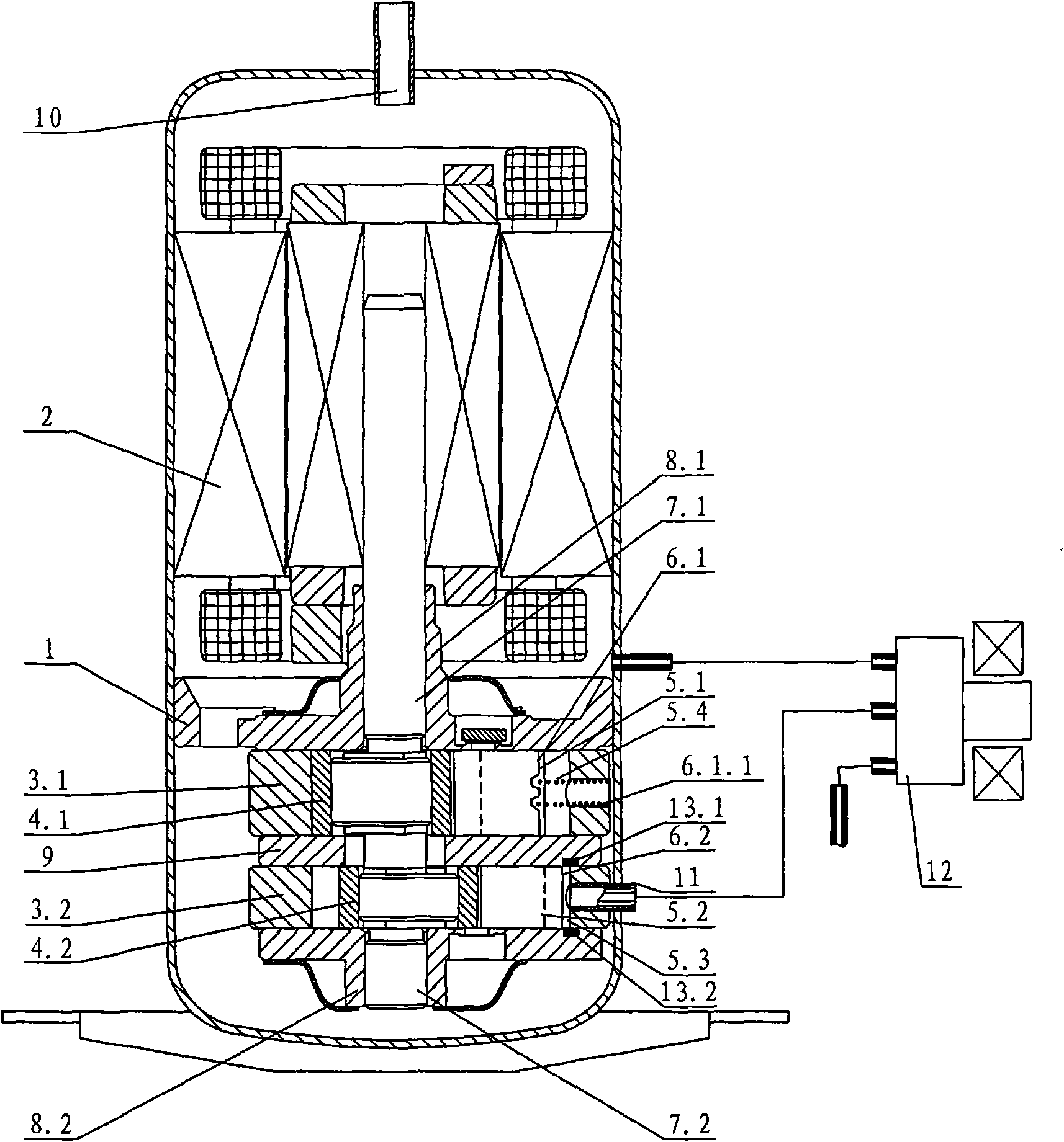
It is mentioned here that when the pressure delivery pipe 11 is under low pressure, that is, when the vane cavity is low pressure, the second vane 6.2 stops in the vane groove 5.2, but actually due to the low pressure in the cylinder 3.2 and the vane cavity will Fluctuations occur, and the second sliding vane 6.2 itself will vibrate due to the operation of the compressor. These two factors will easily cause the second sliding vane 6.2 to protrude into the second cylinder 3.2 and collide with the second piston 4.2. After the collision, bounce back, and collide with the wall of the slide cavity, thus forming a bad noise, see attached Figure 9 , there may even be damage and failure of the slide and piston

Method used


Image

  • Slip sheet control device of rotary compressor
  • Slip sheet control device of rotary compressor
  • Slip sheet control device of rotary compressor

Examples


no. 1 example

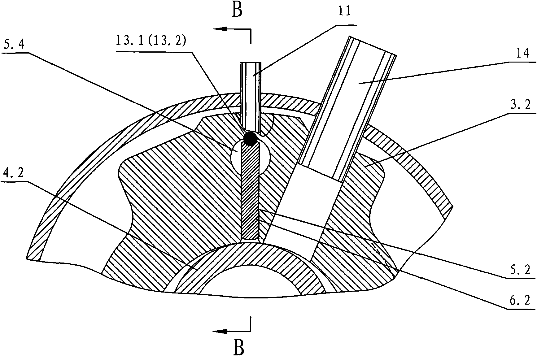
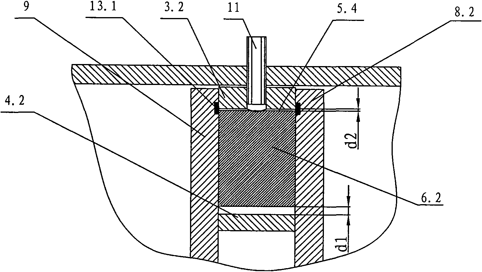
[0034] see Figure 5 , Figure 6 and Figure 9 A small head that moves in the same direction as the second slide 6.2 and improves its movement reliability is provided on the back of the second slide 6.2, and a space is provided on the side of the small head facing the magnet. The purpose of setting the space is to meet the requirements of the above scheme. The simple method is to open two straight cuts between the backs of the second slide 6.2, and design the back section of the second slide 6.2 into a convex shape, that is, the side shape of the small head in the circumferential direction of the second cylinder 3.2 is square , Or, it can also be understood as follows: the section of the small head along the moving direction of the second sliding piece 6.2 is square.

[0035] Figure 5 Among them, when the second sliding piece 6.2 stops working and is at the position that just withdraws from the inner wall of the second cylinder 3.2, the back of the second sliding piece 6....

no. 2 example

[0040] see Figure 7 and Figure 9 , set two oblique cuts on the back of the second sliding plate 6.2, that is, when the side shape of the small head in the circumferential direction of the second cylinder 3.2 is trapezoidal, its implementation effect is the same as that of the first embodiment, but the processing performance of the sliding plate is improved. That is, the processing cost is low and the processing efficiency is high.

[0041] Of course, concave arc-shaped grooves can also be provided on the upper and lower sides of the back of the second sliding piece 6.2, and the same effect as that of the first embodiment can also be achieved.

[0042] See the first embodiment for the rest of the undescribed parts, and will not repeat them here.


PUM


Abstract

The invention discloses a slip sheet control device of a rotary compressor, comprising a compression assembly and a motor assembly which are arranged in a sealing housing, wherein the compression assembly comprises a first cylinder, a second cylinder, an eccentric crank shaft, an upper bearing, a lower bearing and a middle clapboard arranged between the first cylinder and the second cylinder; the upper bearing and the lower bearing support the eccentric crank shaft; a first piston, a second piston, a first slip sheet slot and a second slip sheet slot are respectively arranged in each cylinder; a fist slip sheet and a compression spring are arranged in the first slip slot, a second slip sheet is arranged in the second slip sheet slot, and the second slip sheet slot is communicated with a slip sheet cavity which is communicated with a pressure transmission tube; a magnet absorbing and braking the second slip sheet is arranged on the bearing or the middle clapboard in the slip sheet cavity at the back of the second slip sheet; the back of the second slip sheet is provided with a small head which moves in the same direction with the second slip sheet and improves the movement reliability thereof, and one side of the small head, which faces to the magnet, is provided with a clearance space. The invention has the characteristics of reliable performance, high safety degree and long service life.

Description

technical field [0001] The invention relates to a rotary compressor, in particular to a sliding vane control device of the rotary compressor. Background technique [0002] Common twin-cylinder or multi-cylinder rotary compressors, such as attached figure 1 As shown, a compression assembly 1 and a motor assembly 2 are arranged inside the closed compressor casing. The compression assembly includes two cylinders, respectively the first cylinder 3.1 and the second cylinder 3.2, each cylinder is respectively provided with a first piston 4.1 and a second piston 4.2, and is respectively provided in the first slide groove 5.1 and the second slide groove of the cylinder. The first sliding plate 6.1 and the second sliding plate 6.2 in the plate groove 5.2, the eccentric crankshaft driving the piston, the eccentric crankshaft includes the eccentric crankshaft main shaft 7.1 and the eccentric crankshaft countershaft 7.2, the upper bearing 8.1 and the lower bearing 8.2 supporting the ec...

Claims


Application Information

Patent Timeline
Patent Type & Authority Applications(China)
IPC IPC(8): F04C28/00F04C23/00
Inventor 李华明杨国用方彦飞
Owner GUANGDONG MEIZHI COMPRESSOR
Learn More