
Antiphase coupling elliptic function spiral wave filter

An elliptic function and anti-phase technology, which is applied in the field of communication, can solve problems such as difficult engineering, large manpower and material resources, and complex design, and achieve the effects of simplified circuit design, high-performance suppression, and simple structure

Active Publication Date: 2010-01-20
XIAN INSTITUE OF SPACE RADIO TECH
View PDF0 Cites 11 Cited by
  • Summary
  • Abstract
  • Description
  • Claims
  • Application Information

AI Technical Summary

Problems solved by technology

But the disadvantage is that the design is complicated, and there are three or four types of coupling. It takes a lot of manpower and material resources to develop such a filter, and it is difficult to engineer. In addition, because it is foldable, the volume becomes large and the practicability is poor.

Method used


Image

  • Antiphase coupling elliptic function spiral wave filter
  • Antiphase coupling elliptic function spiral wave filter
  • Antiphase coupling elliptic function spiral wave filter

Examples


Embodiment Construction

[0036] The present invention will be further described below in conjunction with an example. The example takes a single-group CQ structure as an example, and the rest of the structural principles are the same.

[0037] Such as Figure 8 , 9 As shown in , 10, the anti-phase coupling elliptic function helical filter includes a helical filter cavity 1, a helical filter cover plate 2, an SMA connector 3, a frequency adjustment screw 4, a coupling adjustment screw 5, a blocking plate 6, and 4 resonances device and an anti-phase coupling mechanism.

[0038] The spiral filter cavity 1 is mechanically connected with the spiral filter cover plate 2 to form a shielded structure. The spiral filter cavity 1 and the spiral filter cover plate 2 are made of metal materials.

[0039] The SMA connector 3 is installed on both sides of the helical filter cavity 1, and the guide post at the center of the SMA connector 3 is used to connect the input and output terminals of the coil to transmit ...


PUM


Abstract

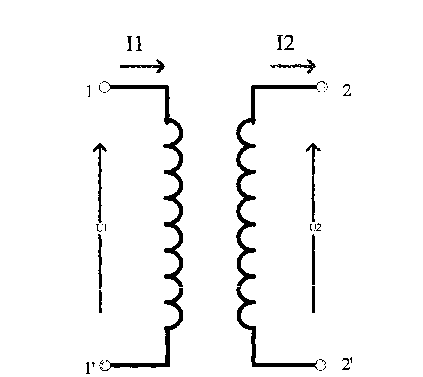
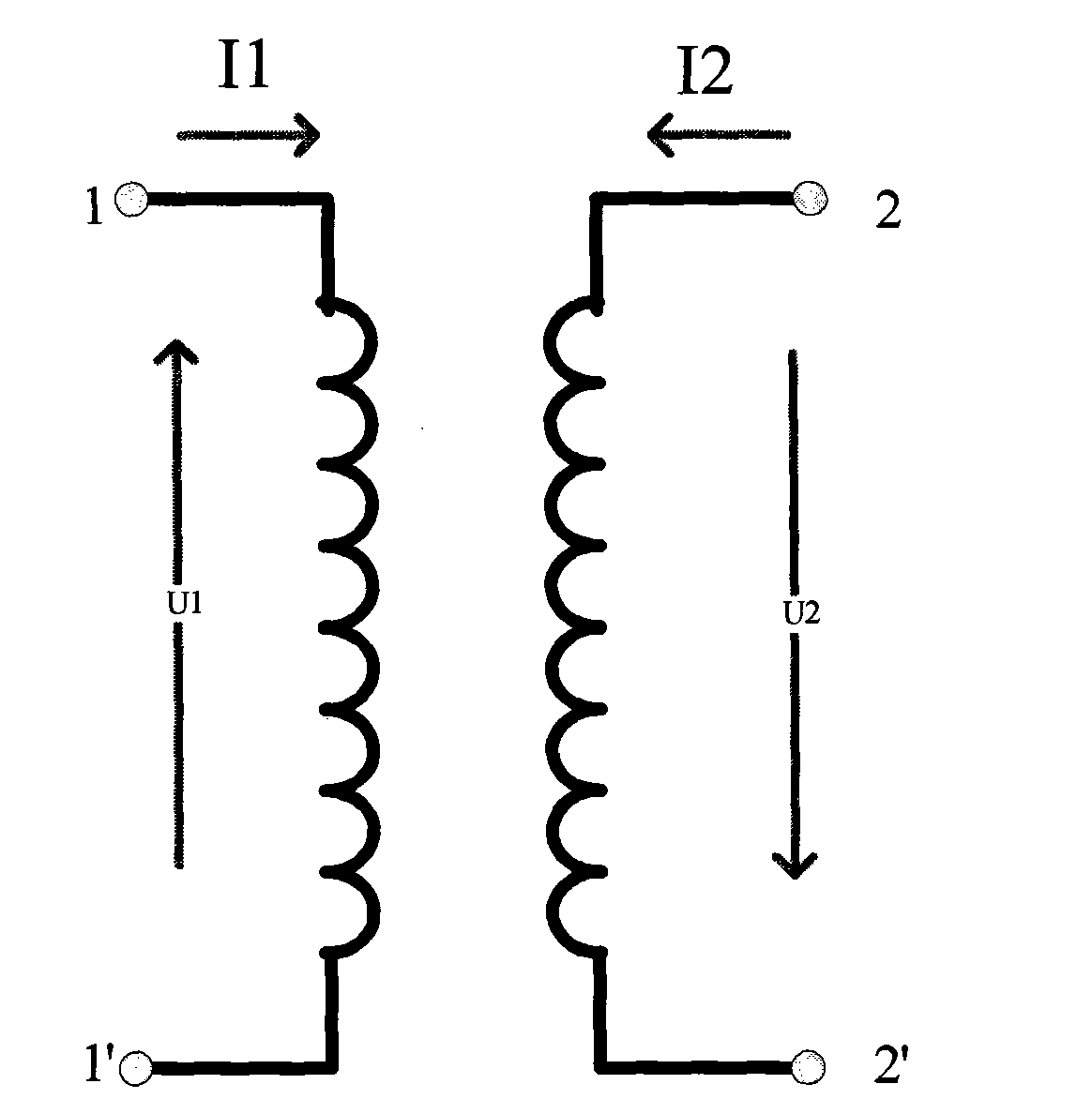
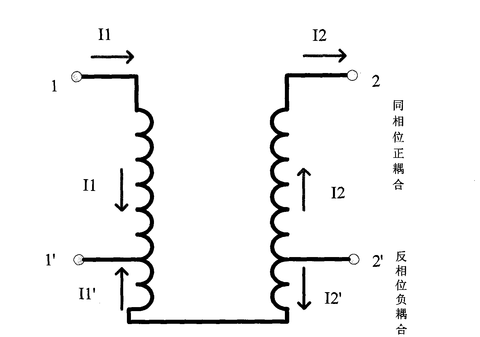
The invention relates to an antiphase coupling elliptic function spiral wave filter which comprises a spiral wave filter cavity, a spiral wave filter cover plate, an SMA joint, a frequency debugging screw, a coupling debugging screw, a block plate, n resonators and m antiphase coupling mechanisms, wherein n is an integer more than or equal to 3, and m is an integer more than or equal to 1; each resonator comprises a polytetrafluoroethylene medium framework and a positive phase spiral coil, wherein the positive phase spiral coil is wound on the polytetrafluoroethylene medium framework; each antiphase coupling mechanism includes two antiphase spiral coils and an antiphase feed cable, wherein the antiphase spiral coils are wound on the polytetrafluoroethylene medium framework along the reverse direction from the earthing position of the positive phase spiral coil, and the winding direction is opposite to the direction of the positive phase spiral coil, so that antiphase current is generated; on the premise of not increasing the volume, the weight and the loss, a pair of or a plurality of attenuation pole points are formed outside a band of the wave filter, so that inhibition outside the band can be greatly improved. The spiral wave filter has the advantages of novel and compact structure, small volume, light weight and large power capacity.

Description

technical field [0001] The invention relates to an anti-phase spiral filter, in particular to a multi-coupling elliptic function spiral filter, which belongs to the technical field of communication. Background technique [0002] There are few reports on elliptic function helical filters, mainly due to the particularity of helical resonators, and there is no practical and effective design software, which makes the design and implementation very difficult. In 2000, Lora Corporation of the United States proposed a half-wavelength dual-mode elliptic function helical filter. Its structural feature is to realize a cavity dual-mode technology on a helical resonator. Although the number of resonators is halved, the half-wavelength resonator is used again The height of the spiral resonator is doubled; in addition, the coupling between the dual-mode resonators depends on the 45-degree tuning screw. When the number of coil turns is large (for example, when it is more than 10), the diam...

Claims


Application Information

Patent Timeline
IPC IPC(8): H01P1/207
Inventor 王小林毛国振倪大宁邱润锁吴须大
Owner XIAN INSTITUE OF SPACE RADIO TECH
Learn More