
Fuselage of an aircraft or spacecraft of CRP/metal hybrid construction with a metal framework

一种金属框架、框架构件的技术,应用在机身、飞机零件、金属材料涂层工艺等方向,能够解决目的冲突等问题,达到高性能、克服缺点和局限性的效果

Inactive Publication Date: 2013-06-12
AIRBUS OPERATIONS GMBH
View PDF3 Cites 0 Cited by
  • Summary
  • Abstract
  • Description
  • Claims
  • Application Information

AI Technical Summary

Problems solved by technology

[0008]The foregoing prior art results in a conflict of purpose that cannot be resolved without the introduction of new technology

Method used


Image

  • Fuselage of an aircraft or spacecraft of CRP/metal hybrid construction with a metal framework
  • Fuselage of an aircraft or spacecraft of CRP/metal hybrid construction with a metal framework
  • Fuselage of an aircraft or spacecraft of CRP/metal hybrid construction with a metal framework

Examples


Embodiment Construction

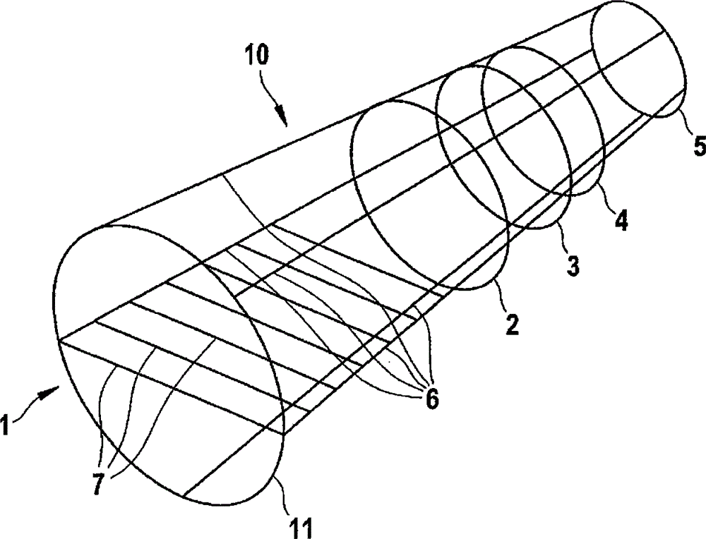
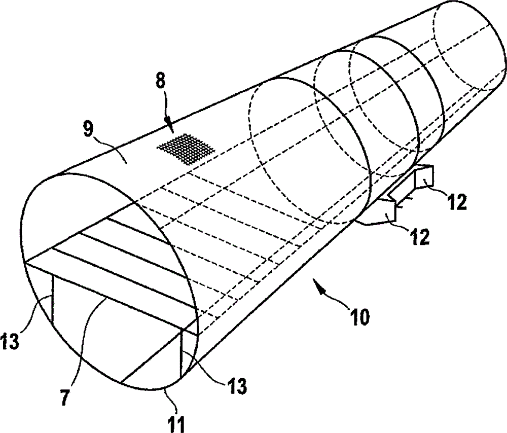
[0043] Figure 1a An aircraft fuselage 10 according to the invention is schematically depicted. The figure firstly shows the frame 1 of the aircraft fuselage 10 without the outer panels 9 . Said frame 1 extends, for example, from the end of the rear fuselage to the start of the nose section.

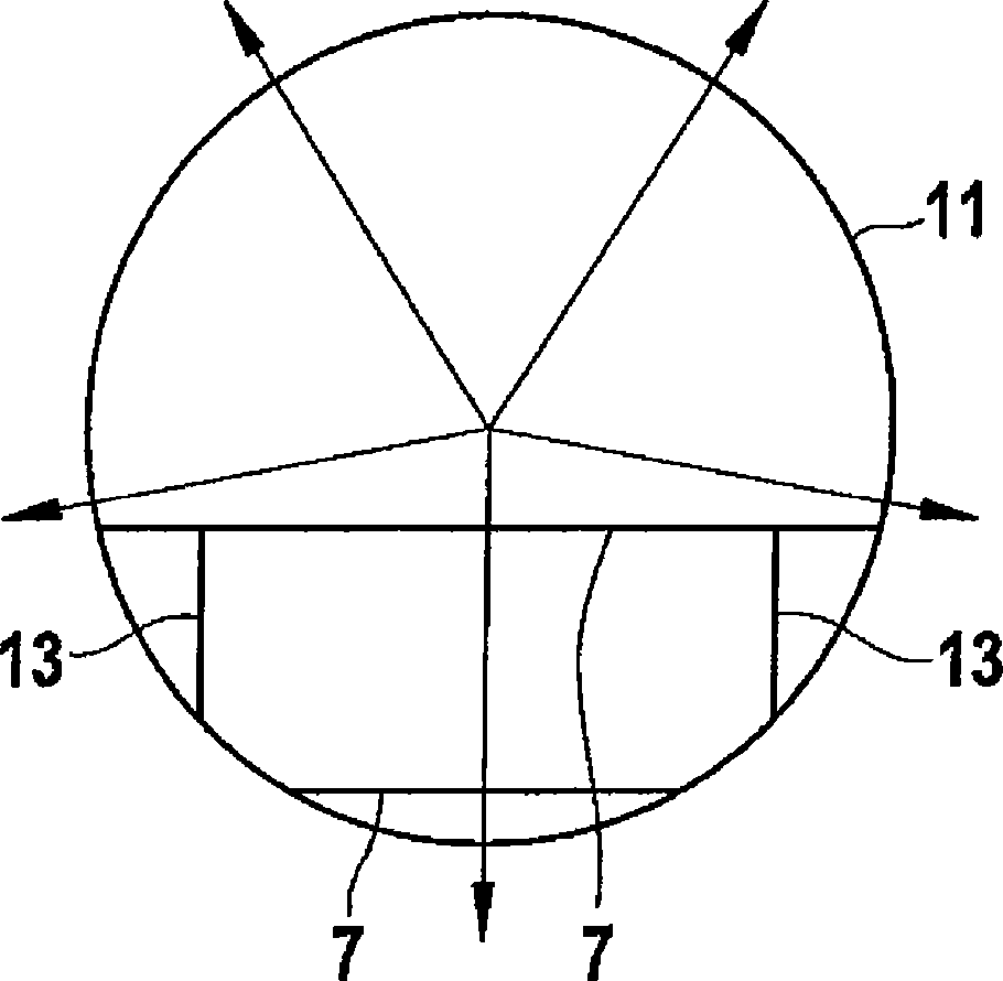
[0044] The frame 1 has a frame member 11 for the nose section, a frame member 2 for the wing connection of the front spar (CWB front load bearing frame) and a wing connection for the rear spar Frame member 3 (CWB rear load frame). Furthermore, there is a frame member 4 for the rear end (bulkhead) of the landing gear well (MLG rear bulkhead frame) and a frame member 5 for the rear fuselage end (framed rear pressure dome). The frame 1 also has a plurality of cross braces 7 of the passenger floor (holywood floor beams), which are connected to shell joints 6 in the longitudinal direction (longitudinal panel joints). Said cross brace 7 as shown in FIG. 1 is given purely by way of example ...


PUM


Abstract

The present invention provides an inherently rigid fuselage of an aircraft or spacecraft comprising shell elements or fuselage barrels of CRP construction, wherein the shell elements or fuselage barrels each have an outer skin and an inner skin, which each at least partially or completely consist of a CRP material, wherein a composite core element is provided between the outer skin and the inner skin, and wherein the fuselage in the interior has a metal framework which is connected to the shell elements or fuselage barrels.

Description

technical field [0001] The invention relates to an aircraft fuselage of CRP / metal composite structure, wherein the aircraft fuselage is provided with a metal frame. Background technique [0002] Aircraft fuselages are generally constructed from metal panels in the prior art. However, it has the disadvantage that the metal body has a relatively high weight. [0003] Conversely, an aircraft fuselage of conventional monolithic CRP construction can save considerable weight compared to a metal fuselage. However, the CRP structure almost completely loses this advantage if it is to have the ability to achieve shielding of electromagnetic interference and pre-treatment of electrical system installations. On the contrary, the metal body automatically comes with such ability to shield electromagnetic interference. [0004] In most recent developments, there have been attempts to counteract this disadvantage by using metal framing members. However, the close spacing of the frame m...

Claims


Application Information

Patent Timeline
Patent Type & Authority Patents(China)
IPC IPC(8): B64C1/00
CPCB64C1/068C23C2/04
Inventor 米夏埃尔·柯拉克斯沃尔夫迪特里希·多尔茨斯基汉斯-彼得·温策尔拉尔夫·赫尔曼
Owner AIRBUS OPERATIONS GMBH
Learn More