

Film-forming apparatus and film-forming method
A film-forming device and film-forming chamber technology, applied in ion implantation plating, metal material coating process, coating and other directions, can solve the problem of not getting ITO film, etc., and achieve uniform film-forming atmosphere and stable film quality. Maintenance, the effect of small variation in characteristics
- Summary
- Abstract
- Description
- Claims
- Application Information
AI Technical Summary
Problems solved by technology
Method used
Image

Examples
no. 1 approach
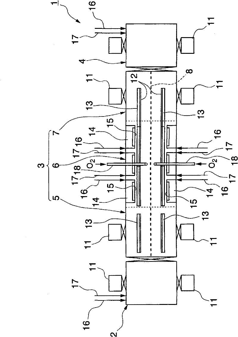
[0078] figure 1 It is a schematic diagram of the in-line reactive sputtering apparatus of the first embodiment of the present invention.
[0079] The sputtering apparatus 1 is composed of a front chamber 2, a sputtering film forming chamber 3, and a rear chamber 4 that also serves as a reversal chamber. The sputtering film formation chamber 3 is composed of three areas of an inlet side area 5, a sputtering area 6 and an outlet side area 7. The center positions in the width direction of these entrance-side regions 5, sputtering regions 6, and exit-side regions 7 are provided for dividing these regions into forward paths ( figure 1 Middle and lower side) and loop ( figure 1 Upper middle side) Spacer 8 of two systems.
[0080] In addition, in the sputtering device 1, in the case of a loop, the front chamber 2 functions as a back chamber, and the rear chamber 4 functions as an front chamber. Here, for convenience, the forward path is referred to as the front chamber 2 and Back room 4....
no. 2 approach
[0123] Figure 8 It is a schematic diagram of the in-line reactive sputtering apparatus of the second embodiment of the present invention. The difference between the sputtering device 31 of this embodiment and the sputtering device 1 of the first embodiment is as follows. That is, in the sputtering apparatus 1 of the first embodiment, the carrier 12 is transported back and forth, and vacuum pumps 11 are provided on both sides of the inlet side area 5 and the outlet side area 7 of the sputtering film forming chamber 3. A gas introduction pipe 18 for film quality adjustment is provided in the center of the area 6. In contrast, in the sputtering apparatus 31 of this embodiment, the carrier 12 is transported in only one direction, and the sputtering film forming chamber 32 is provided on each side of the inlet side area 5 and the outlet side area 7 In the vacuum pump 11, a gas introduction pipe 18 for film quality adjustment is provided in the vicinity of the wall surface peripher...
no. 3 approach
[0126] Picture 9 It is a schematic diagram of the in-line reactive sputtering apparatus of the third embodiment of the present invention. The difference between the sputtering device 41 of this embodiment and the sputtering device 31 of the second embodiment is as follows. That is, in the sputtering device 31 of the second embodiment, the vacuum pump 11 is provided on each side of the inlet side area 5 and the outlet side area 7, and the wall surface of the side facing the vacuum pump 11 in the sputtering area 33 A gas introduction pipe 18 for film quality adjustment is provided near the end. In contrast, in the sputtering device 41 of this embodiment, a vacuum pump 11 is provided on each side of the inlet side area 5 and the outlet side area 7 of the sputtering film forming chamber 42, and the vacuum pump 11 is installed in the sputtering area 43. 11 is provided with a gas inlet pipe 18 for film quality adjustment at the center of the wall surface on the side facing each oth...
PUM
 Abstract
Description
Claims
Application Information