Transfer printing type glue dispensing method

A technology of pad printing and glue dispensing, which is applied in the direction of spraying devices, coatings, and devices for coating liquid on the surface, etc. It can solve the problems of excessive glue volume, unqualified products, semi-finished products overflowing glue, etc., and achieve the effect of uniform glue volume

Inactive Publication Date: 2010-01-27
ICHIA TECH
View PDF0 Cites 5 Cited by
  • Summary
  • Abstract
  • Description
  • Claims
  • Application Information

AI Technical Summary

Problems solved by technology

[0004] Since the amount of gas delivered by the air compressor to each glue spray head 70 is not the same, some glue spray heads 70 will spray a large amount of glue, while others will spray a small amount of glue, which makes the semi-finished product easy to bond when bonding. Glue overflow phenomenon, or incomplete bonding, resulting in substandard products

Method used


Image

  • Transfer printing type glue dispensing method
  • Transfer printing type glue dispensing method
  • Transfer printing type glue dispensing method

Examples


Embodiment Construction

[0053] The technical content and detailed description of the present invention are described as follows in conjunction with the accompanying drawings.

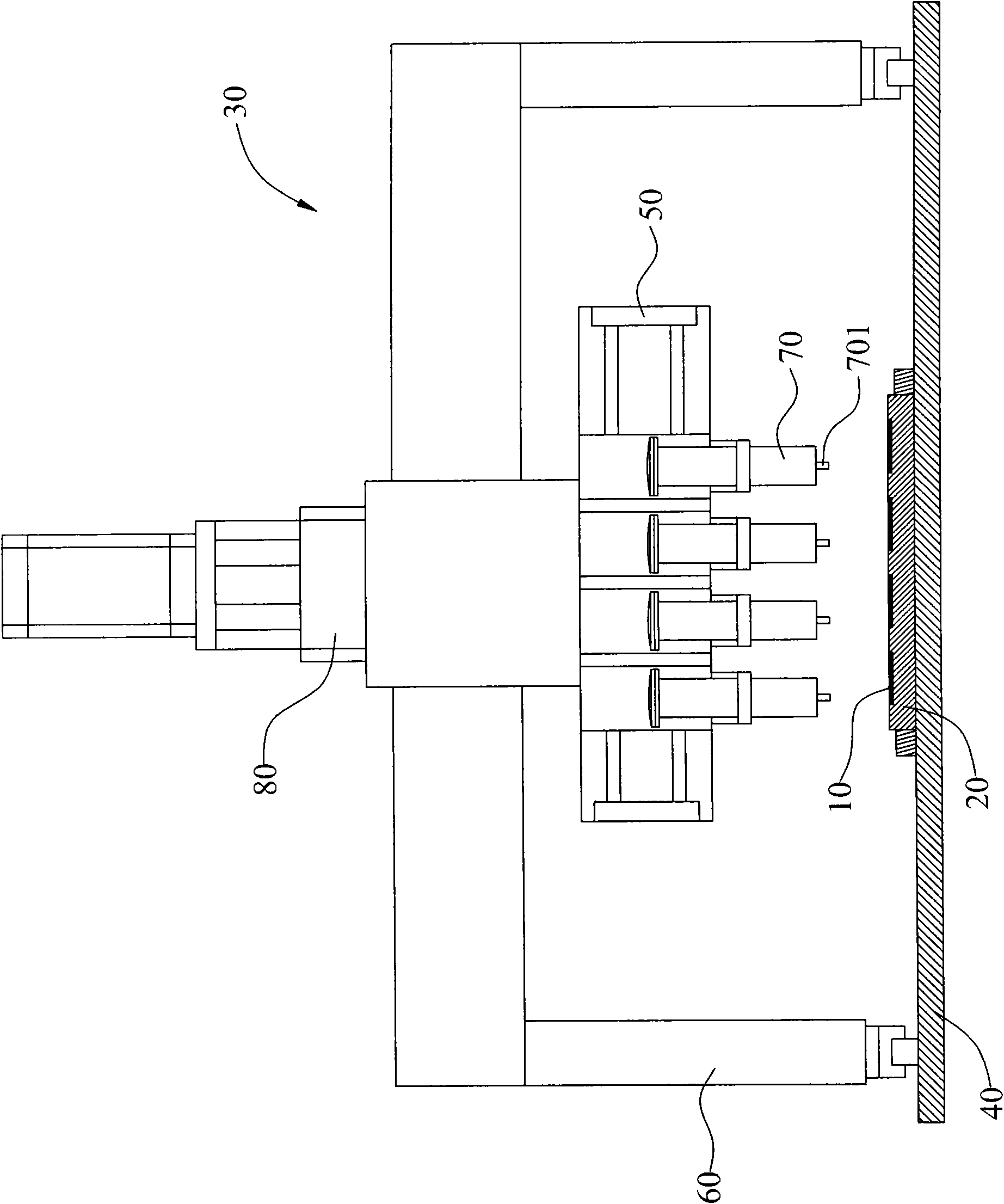
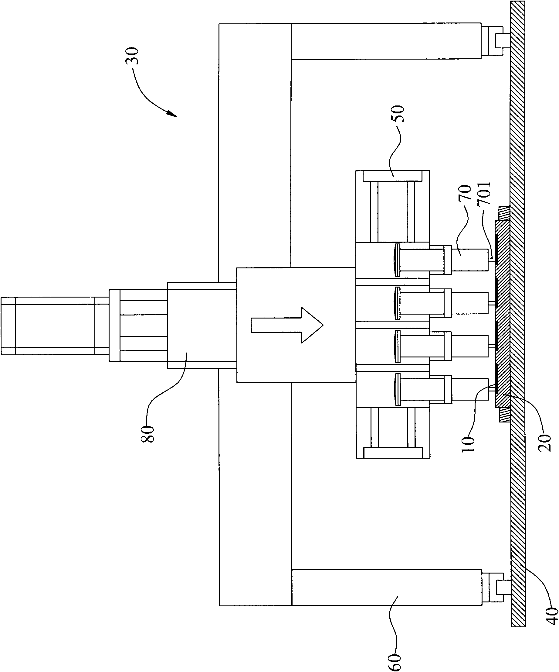
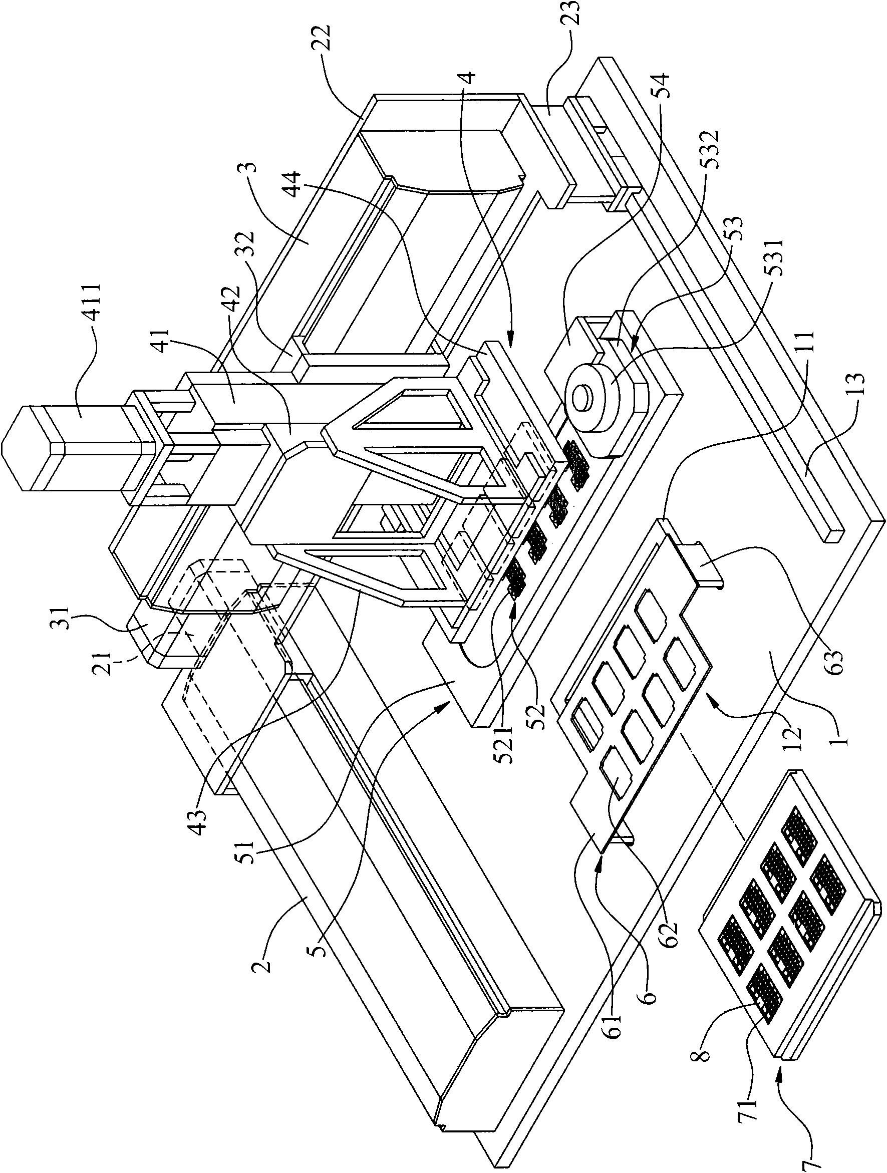
[0054] refer to Figure 2a , Figure 2b , are respectively the three-dimensional schematic diagram and the anvil block side view schematic diagram of the pad printing type glue dispenser of the present invention. Such as Figure 2a , Figure 2b Shown: the pad printing dispensing method of the present invention has a glue dispensing machine, which includes: a loading platform 1, a Y-axis moving mechanism 2, an X-axis moving mechanism 3, a pad printing module 4, a glue storage mechanism 5, The pressing mechanism 6 and the clamp plate 7.

[0055] The carrying platform 1 is arranged on the glue dispenser, and has a flat-bottomed inverted U-shaped convex strip 11 on it, and the convex strip 11 encloses a placement area 12 for placing the fixture disc 7 . In addition, a slide rail 13 is provided on the convex line 11 side.

[...


PUM


Abstract

The invention provides a transfer printing type glue dispensing method. The method comprises the following steps of: firstly, preparing a fixture plate and a glue dispenser; placing two or more glued objects on the fixture plate; sending the fixture plate into the glue dispenser; carrying out glue filling action with a glue storage mechanism of the glue dispenser; controlling a Z-axis moving mechanism on a transfer printing module to act with an external control box, and moving an anvil block on the transfer printing module to the glue storage mechanism to dip glue; controlling an X-axis moving mechanism and a Y-axis moving mechanism to act with a control box, and moving the transfer printing module dipped with the glue to the fixture plate; and driving the Z-axis moving mechanism on the transfer printing module with the external control box, and printing the glue dipped on the anvil block onto the glued objects.

Description

technical field [0001] The invention relates to a glue dispensing method, especially a pad printing glue dispensing method. Background technique [0002] The thin key panel structure has become an indispensable hardware structure for portable electronic devices. The thin key panel structure generally includes a key cap layer, a light guide layer, a rubber layer, a metal shrapnel layer, and a printed circuit board. When the structure of the key panel is combined, some layers must be glued on the surface of the layer by a glue dispenser in order to bond with the structure of another layer. [0003] Therefore, when the traditional key panel structure semi-finished product 10 is dispensing (such as Figure 1a , Figure 1b shown), the semi-finished product 10 is placed on the fixture plate 20, and then the fixture plate 20 is sent to the loading platform 40 of the glue dispenser 30, and the X-axis moving mechanism 50 and the Y-axis moving mechanism 60 are controlled by an exter...

Claims


Application Information

Patent Timeline
Patent Type & Authority Applications(China)
IPC IPC(8): B05D5/02B05B13/04
Inventor 叶秋余林威良郑嘉胜黄裕正
Owner ICHIA TECH
Why Eureka
Try Eureka