Direct-drive type feeding device of milling machine

A feeding device, transmission type technology, applied in electromechanical devices, feeding devices, milling machine equipment, etc., can solve the problems of small adjustable range, high manufacturing cost, inconvenient maintenance, etc., to reduce production costs, reduce failure rates, The effect of reducing maintenance costs

Inactive Publication Date: 2010-01-27
烟台顺和机电设备有限公司
View PDF0 Cites 6 Cited by
  • Summary
  • Abstract
  • Description
  • Claims
  • Application Information

AI Technical Summary

Problems solved by technology

[0003] In order to overcome the deficiencies of the prior art, the present invention provides a milling machine direct-drive feeding device, which solves the technical problems of low moving spe

Method used


Image

  • Direct-drive type feeding device of milling machine

Examples


Embodiment Construction

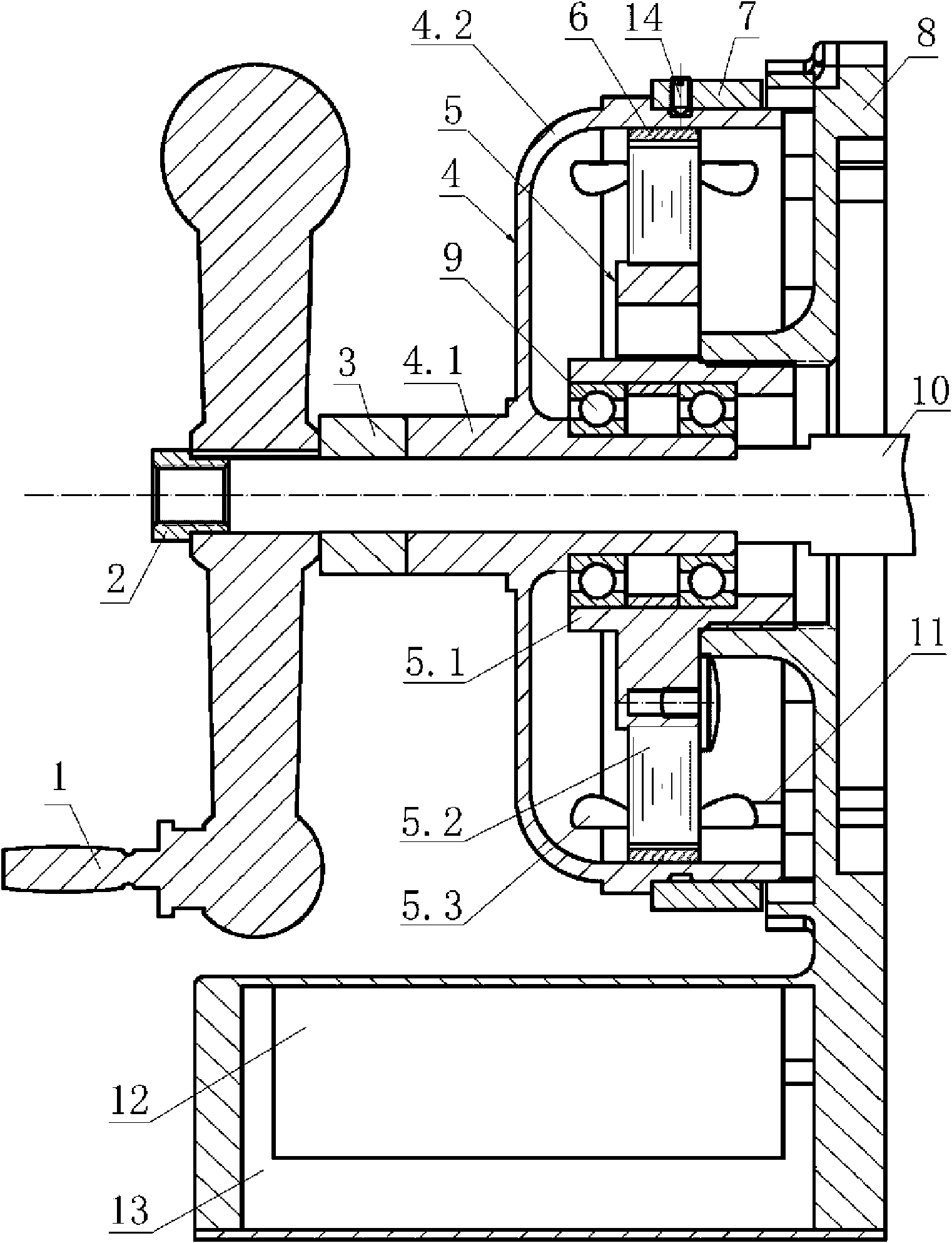
[0024] see example figure 1 As shown in the figure, this direct-drive feed device for a milling machine includes a low-speed motor that is driven and connected to the lead screw of the milling machine table and a motor controller that is connected to the low-speed motor. The low-speed motor is fixed on the motor base 8, and the low-speed motor is no Brushed DC servo motor, which includes a rotor 4 and a stator 5; the inner ring shaft sleeve 4.1 of the rotor is directly sleeved on the milling machine table screw 10 and is keyed to the milling machine table screw, and the outer shell 4.2 of the rotor is from the inner ring shaft of the rotor. The sleeve 4.1 extends out to form a cup-shaped rotor cover outside the stator 6 and ends at the outside of the motor base; the inner wall of the rotor shell 4.2 is glued with a permanent magnet 6; the inner ring sleeve 5.1 of the stator is sleeved on the rotor through the bearing 10 On the outside of the inner ring bushing, the stator coil...


PUM


Abstract

The invention relates to a direct-drive type feeding device of a milling machine, comprising a low-speed motor and a motor controller, wherein the low-speed motor is connected with a screw rod of a worktable of the milling machine in a driving mode, the motor controller is connected with the low-speed motor, the low-speed motor is a brushless DC servomotor and comprises a rotor and a stator, an inner ring shaft sleeve of the rotor is directly sleeved on the screw rod of the worktable of the milling machine and connected with the screw rod of the worktable of the milling machine by keys, an outer shell of the rotor extends out of the inner ring shaft sleeve of the rotor to form a cup-shaped rotor, the cup-shaped rotor is covered outside the stator and stopped outside a motor base, and the inner side of the outer shell of the rotor is bonded with a circle of permanent magnet steel. The direct-drive type feeding device directly drives the screw rod of the worktable of the milling machine to rotate by the low-speed motor, does not need any speed reducing device, directly uses the screw rod as a rotor shaft of an external rotor motor so as to lead the shaft output torsion of the motor to directly act on the screw rod of the worktable and has small volume, low noise, large force moment, high rotating speed, convenient installation, flexible and simple operation, attractive appearance, smooth operation, and the like.

Description

technical field [0001] The invention belongs to the field of mechanical processing equipment, in particular to a power device for driving the rotation of a lead screw of a milling machine table. Background technique [0002] There are two ways for the traditional milling machine to realize the movement of the worktable. One is to use the main motor to drive the lead screw of the worktable to rotate through gear transmission to realize the movement of the worktable. This kind of moving method has high manufacturing cost, low moving speed and small adjustable range. The efficiency is low, the maintenance is cumbersome, the supply of accessories is inconvenient, and the production is often delayed. Second, the mechatronics structure with brushed AC and DC motor acceleration and deceleration is placed on the side of the worktable, and the lead screw of the worktable is driven to rotate through gear transmission. Realize table movement. Although this transmission method is more ...

Claims


Application Information

Patent Timeline
IPC IPC(8): B23Q5/36B23C9/00H02K29/00H02K7/10
Inventor 史玉福于立东
Owner 烟台顺和机电设备有限公司
Why Eureka
Try Eureka