Cutting device

A cutting device and component technology, applied in the direction of fine working devices, working accessories, stone processing equipment, etc., can solve the problem of device quality degradation and achieve the effect of preventing quality degradation

Inactive Publication Date: 2010-01-27
DISCO CORP
View PDF6 Cites 6 Cited by
  • Summary
  • Abstract
  • Description
  • Claims
  • Application Information

AI Technical Summary

Problems solved by technology

[0007] However, since cutting chips are mixed in the cutting fluid, if high-pressure air is sprayed on the surface of the wafer in order to remove the cutting fluid, the chips will dry and adhere firmly to the pads of the device, thereby deteriorating the quality of the device. question

Method used


Image

  • Cutting device
  • Cutting device
  • Cutting device

Examples


Embodiment Construction

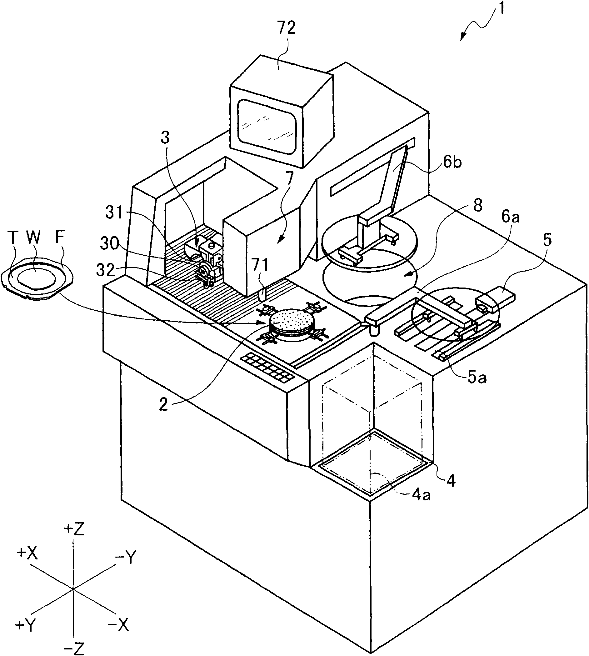
[0021] figure 1 The cutting device 1 shown is a device for cutting a wafer held on a chuck table 2 by a cutting member 3 . At the front of the cutting apparatus 1, there is a cassette loading area 4 where a wafer cassette 4a for storing wafers to be cut is placed. Further, a loading / unloading member 5 for loading and unloading wafers from and into the wafer cassette 4 a is disposed on the rear side of the cassette loading area 4 .

[0022] A temporary storage area 5 a is provided between the cassette loading area 4 and the loading / unloading member 5 as an area where wafers are temporarily loaded. In addition, a first transfer member 6 a for transferring a wafer between the temporary storage area 5 a and the chuck table 2 is disposed near the temporary storage area 5 a.

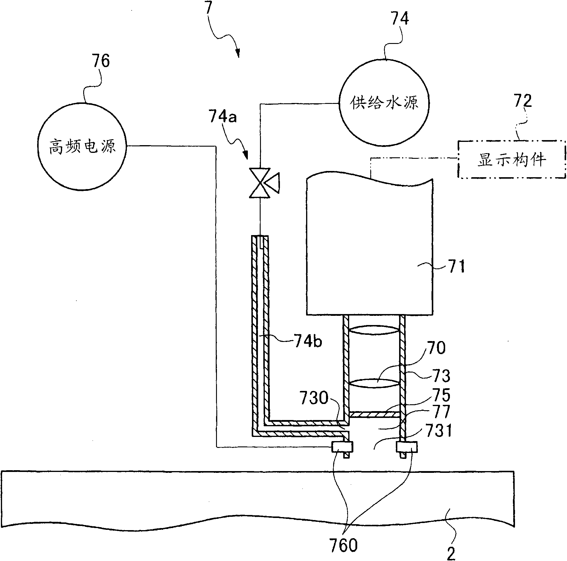
[0023] The chuck table 2 is movable in the X-axis direction, and an alignment member 7 for imaging the wafer held on the chuck table 2 to detect a region to be cut is disposed above the movement path of the ...


PUM


Abstract

The invention provides a cutting device which supplies an cutting liquid and cuts the wafer, can reliably grasp the cutting groove state even if the cutting liquid adheres on the wafer and prevent the chips from adhering on the wafer, thus not reducing the device quality. A groove inspection member (7) forming the cutting device has an object lens (70); a shooting member (71) for shooting with the object lens; a display member (72) for displaying the image obtained by the shooting member; a cylindrical shell (73) surrounding the object lens, having an opening part toward the wafer and forming a gap between the opening part and the wafer; an partition wall (75) arranged between the object lens and the opening part; a water storage chamber (77) composed of the partition wall, the cylindrical shell and the opening part; and a supply water source (74) for supplying water to the interior of the water storage chamber. A clear image can be obtained and is irrelative to the adhesion of the cutting liquid through continuously supplying water to the water storage chamber and shooting and the chips are kept not dry to prevent them from firmly adhering.

Description

technical field [0001] The present invention relates to a cutting device including a groove inspection means capable of imaging and inspecting grooves formed on a wafer by cutting. Background technique [0002] With regard to a wafer formed with a plurality of devices such as IC (Integrated Circuit: Integrated Circuit) and LSI (Large Scale Integration: Large Scale Integrated Circuit) divided by the planned dividing line on the surface, the dividing line is cut by using a cutting device. It is divided into individual devices and used in various electronic devices. [0003] A cutting device used for dividing a wafer, etc. includes: a chuck table, which holds a wafer; a cutting member, which has a rotatable cutting tool; an imaging member, which takes an image of a cutting groove formed by cutting; and a display member, It displays the image obtained by the imaging means. After cutting, by taking an image of the state of the cutting groove formed on the planned division line a...

Claims


Application Information

Patent Timeline
Patent Type & Authority Applications(China)
IPC IPC(8): B28D5/00B28D7/00B28D7/02B28D7/04
Inventor 关家一马
Owner DISCO CORP
Why Eureka
Try Eureka