Vehicle conveying device and vehicle radiation detection system provided with same

A technology for conveying devices and vehicles, which is applied in the direction of vehicle control devices, conveyors, vehicle maintenance, etc., can solve the problems of affecting the conveying efficiency and time consumption of the detected objects, and achieve the effects of improving convenience, quickness of use, and reasonable structure

Active Publication Date: 2010-01-27
NUCTECH CO LTD
View PDF0 Cites 8 Cited by
  • Summary
  • Abstract
  • Description
  • Claims
  • Application Information

AI Technical Summary

Problems solved by technology

In other words, in the prior art, the conveying process of the vehicle used for the detected object is an intermittent operation, which greatly affects the conveying efficiency of the detected object due to the time-consuming operation of re-fixing or loading the card.

Method used


Image

  • Vehicle conveying device and vehicle radiation detection system provided with same
  • Vehicle conveying device and vehicle radiation detection system provided with same
  • Vehicle conveying device and vehicle radiation detection system provided with same

Examples


Embodiment Construction

[0046] The technical solutions of the present invention will be further specifically described below through the embodiments and in conjunction with the accompanying drawings. In the specification, the same or similar reference numerals designate the same or similar components. The following description of the embodiments of the present invention with reference to the accompanying drawings is intended to explain the general inventive concept of the present invention, but should not be construed as a limitation of the present invention.

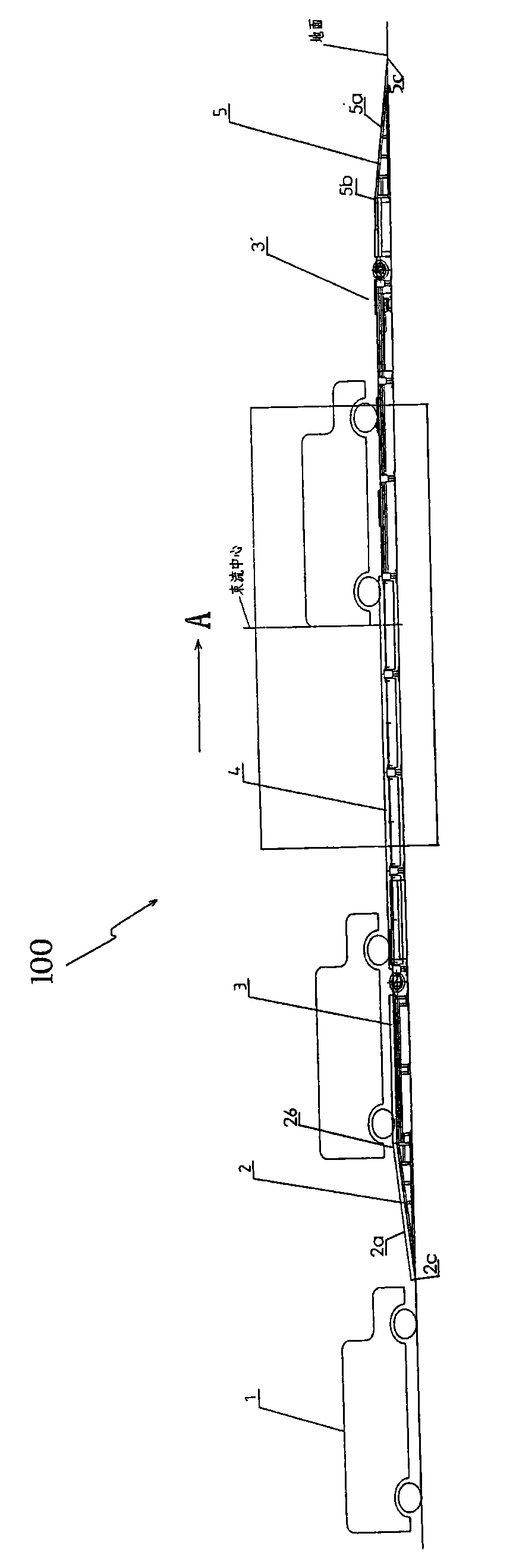
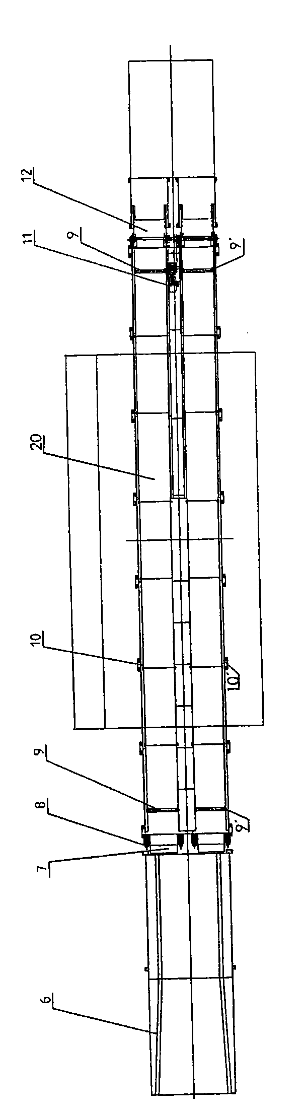
[0047] 1 is a schematic diagram showing the overall structure of a conveying device for a vehicle according to a specific embodiment of the present invention, wherein Figure 1A is a side view showing the conveyor, Figure 1B is a top view showing the conveying device. Referring to Fig. 1, it shows a kind of conveying device that is used for vehicle 1, comprises: vehicle drives into platform 3, and described vehicle enters in the described co...


PUM


Abstract

The invention discloses a conveying device for vehicles, which comprises the following parts: a vehicle driving-in platform through which the vehicles get into the conveying device along the conveying direction; a vehicle driving-out platform through which the vehicles get away from the conveying device along the conveying direction; and a conveying platform which is arranged between the vehicle driving-in platform and the vehicle driving-out platform and comprises a supporting platform forming a bearing surface of the conveying platform and used for supporting wheels of the vehicles in the conveying process, a circulating belt unit arranged on at least one side of the supporting platform so as to move along the conveying direction circularly, and a dragging unit connected to the circulating belt unit to drive the wheels of the vehicles to pass through the supporting platform along the conveying direction. By adopting the technical scheme, the conveying platform adopts the circulating belt unit moving along the conveying direction circularly to drive the dragging unit to drive the vehicles to pass through the conveying platform along the conveying direction, so the continuity of the conveying operations is achieved, and then the conveying efficiency of the conveying device can be improved.

Description

technical field [0001] The invention relates to a conveying device, in particular to a conveying device for vehicles, which can be used in the technical field of logistics transportation, and is especially suitable for vehicles, such as small passenger cars. In addition, the present invention also relates to a vehicle radiation detection system with the above-mentioned vehicle conveying device, which can be used in the technical field of radiation scanning detection, and is especially suitable for the occasion of performing radiation detection on vehicles. Background technique [0002] Radiation imaging detection system is necessary detection equipment for important departments such as customs, civil aviation airport and railway system. Generally, the radiation imaging detection system includes a radiation source, such as an X or isotope ray source; a detector device, such as an array detector, capable of receiving radiation passing through an inspected object, such as a veh...

Claims


Application Information

Patent Timeline
Patent Type & Authority Applications(China)
IPC IPC(8): B60S13/00B65G49/00B65G35/00G01N23/04
Inventor 吴玉成何远胡斌梁晋宁唐盛郭振斌
Owner NUCTECH CO LTD
Why Eureka
Try Eureka