Bidirectional synchronous automatic turning flapping-wing aircraft

A two-way synchronous, automatic flip technology, applied in the direction of helicopters, motor vehicles, aircraft, etc., can solve the problems of reducing drag, reducing drag, reducing the force-bearing area of ​​wings, etc., to increase propulsion and lift, and increase the rotation angle. Large, the effect of improving flight efficiency

Inactive Publication Date: 2010-01-27
杨绍河
View PDF1 Cites 20 Cited by
  • Summary
  • Abstract
  • Description
  • Claims
  • Application Information

AI Technical Summary

Problems solved by technology

[0003] At present, the flapping-wing aircraft developed by people mainly has the following defects: 1. Most of the wings can only perform simple flapping up and down, and cannot be turned over automatically. This is far from the actual flying state of flapping animals. When winged animals fly, the wings are not only simple flapping up and down, but also accompanied by complex turning movements; 2. The inner side of the wing is connected to the fuselage as a whole, and it is connected with the fuselage by a "line", which is similar to that of birds and insects. Wings are also very different. Whether it is a bird or an insect, their wings are connected to the body through the wing root, which is a "point" connection instead of a "line" connection, so the wings have a good degree of freedom (bat's The wings and the body are in "line" contact, because the wings are elastic membranes, so they have a degree of freedom, which is different from birds and insects); 3. Most of the wings are designed in one piece, and when the wings flutter up and down, they cannot be adjusted according to needs The force bearing area of ​​the wing reduces the resistance. The wings of birds can expand and contract when flapping. There is a certain gap between the main and aileron. When flapping down, the gap is closed. Open, the resistance is small, which is good for generating lift
Due to the elastic connection between the two sections of span-wise beams, this design can reduce the force area of ​​the wing when it flaps upwards to a certain extent, thereby reducing the resistance of the upwards flapping. No gap is still a whole, so the way of opening the gap between the wings cannot be used to further reduce the resistance when the wings are flapping, which makes the flying efficiency of the flapping wing aircraft not ideal

Method used


Image

  • Bidirectional synchronous automatic turning flapping-wing aircraft
  • Bidirectional synchronous automatic turning flapping-wing aircraft
  • Bidirectional synchronous automatic turning flapping-wing aircraft

Examples


Embodiment 1

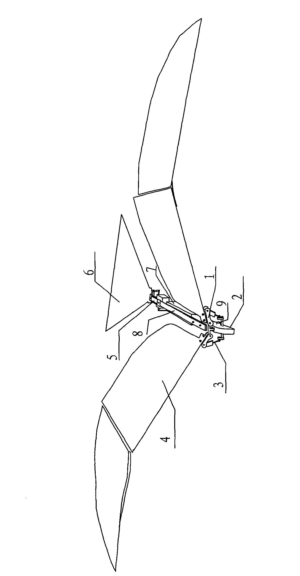
[0037] The two-way synchronous automatic flip flapping wing aircraft of the present invention comprises a flapping wing mechanism 1, a two-way synchronous output reduction mechanism 2, a connecting rod 3, a wing 4, an empennage control mechanism 5, an empennage 6, an equipment main box 7, a fuselage 8 and a motor 9 . After the motor 9 decelerates through the two-way synchronous output reduction mechanism 2, the flapping wing mechanism 1 is driven by the connecting rod 3 to drive the wing 4 to flutter up and down and automatically turn over. When the motor 9 rotated forward or reversed under the action of the control circuit, the wing 4 also fluttered and flipped forward or backward accordingly. Empennage control mechanism 5 controls empennage 6 to flutter up and down or turn left and right. Equipment such as battery, electronic governor and signal receiver are housed in the equipment general box 7. The fuselage 8 is used to connect various components, and there is an include...

Embodiment 2

[0054] Refer to attached Figure 18 :

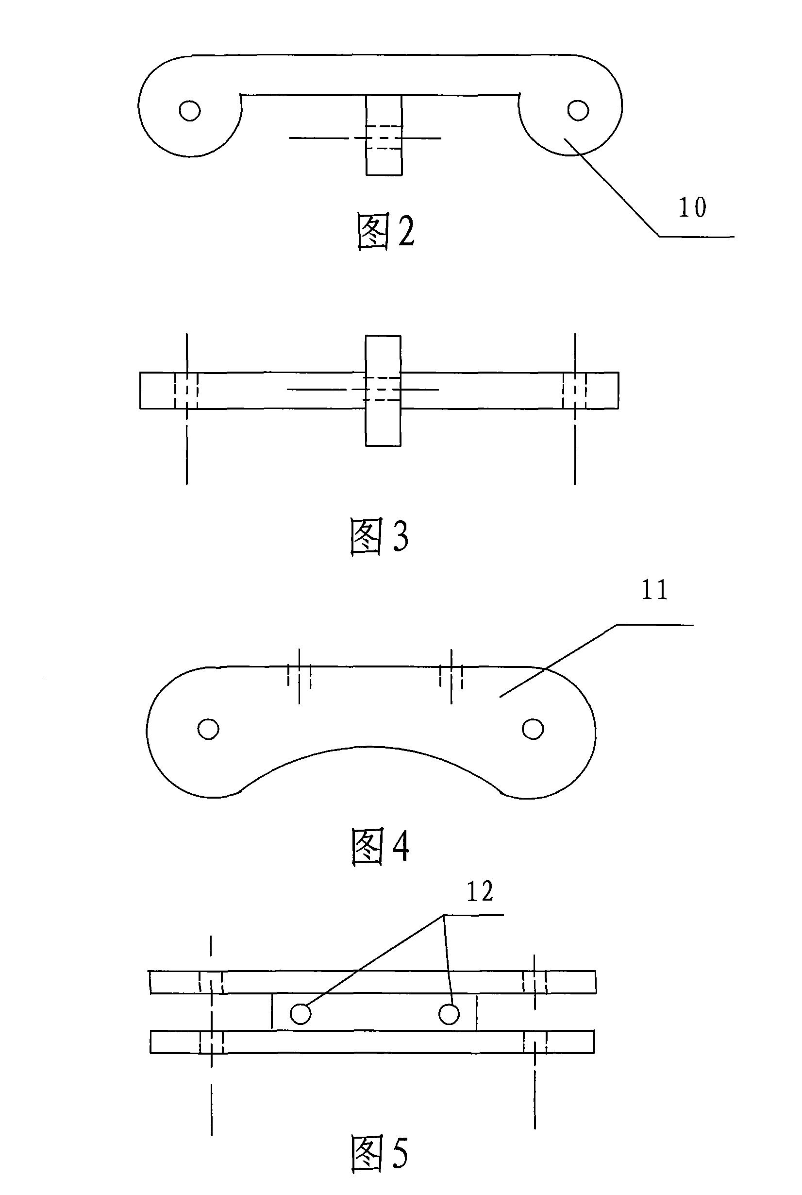
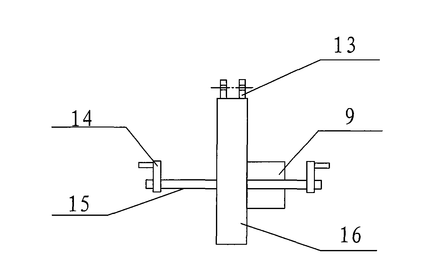
[0055] The wing end 17 of the connecting rod is equipped with a joint bearing, which is connected with the outer end hole of the wing root 11 through a shaft. Two movable joint bearings are respectively installed on both sides of the joint bearing, which are connected to the connecting rod 3 through a spring; Joint bearing is arranged, is connected with crank 14. The 17 bearing holes at the wing end of the connecting rod are perpendicular to the center lines of the 18 bearing holes at the crank end of the connecting rod. This design enables the wing 4 to flip over at a greater angle during flight. Two movable joint bearings and springs are installed on the left and right to protect the joint bearing at the wing end 17 of the middle link from being damaged due to an excessive flip angle. .

[0056] attached Figure 17 It is the schematic diagram of the wing motion of embodiment 2. Refer to attached Figure 17 A brief description of ...


PUM


Abstract

A bidirectional synchronous automatic turning flapping-wing aircraft belongs to the field of astronautic bionic aircraft device, comprising an airframe (8), a wing flapping mechanism (1), a bidirectional synchronous output deceleration mechanism (2), a connecting rod (3), an airfoil (4), an empennage control mechanism (5) and an empennage (6); the bidirectional synchronous automatic turning flapping-wing aircraft is characterized in that the wing flapping mechanism (1) comprises a crossed frame (10) and two wing roots (11); the crossed frame (10) is installed on the front end of the airframe (8) through a bearing; two wing roots (11) are respectively installed on two sides of the crossed frame (10); the airfoil (4) is connected with the wing root (11) through a wing bone; the bidirectional synchronous output deceleration mechanism (2) is connected with the wing root (11) through the connecting rod (3); the empennage control mechanism (5) is installed on the rear end of the airframe (8); the empennage (6) is connected with the empennage control mechanism (5). The airfoil is in spot connection with the airframe and performs the bidirectional synchronous automatic turning with high flying efficiency.

Description

technical field [0001] The invention relates to a two-way synchronous automatic flipping wing plane, which belongs to the field of aerospace bionic aircraft equipment, and specifically relates to a two-way synchronous automatic flipping wing plane. Background technique [0002] In nature, both birds and insects fly by flapping their wings. In addition to providing greater thrust and improving flight efficiency, this flying mode by flapping the wings up and down can also enable the small aircraft to achieve more flexible flight actions. [0003] At present, the flapping-wing aircraft developed by people mainly has the following defects: 1. Most of the wings can only perform simple flapping up and down, and cannot be turned over automatically. This is far from the actual flying state of flapping animals. When winged animals fly, the wings are not only simple flapping up and down, but also accompanied by complex turning movements; 2. The inner side of the wing is connected to ...

Claims


Application Information

Patent Timeline
Patent Type & Authority Applications(China)
IPC IPC(8): B64C33/00B64C33/02
Inventor 杨绍河
Owner 杨绍河
Why Eureka
Try Eureka