Self-locking lifting hook

A hook and self-locking technology, applied in the direction of load hanging components, transportation and packaging, can solve the problems of high labor costs and hidden dangers in production safety, and achieve the effect of avoiding manual support, rational use of functions, and simple structure.

Inactive Publication Date: 2010-01-27
华宝资本有限公司
View PDF0 Cites 1 Cited by
  • Summary
  • Abstract
  • Description
  • Claims
  • Application Information

AI Technical Summary

Problems solved by technology

[0003] The purpose of the present invention is to provide a hook with a self-locking function, which can solve the hidden dangers of production safety and high labor costs of existing ordinary hooks during hanging operations

Method used


Image

  • Self-locking lifting hook

Examples


Embodiment Construction

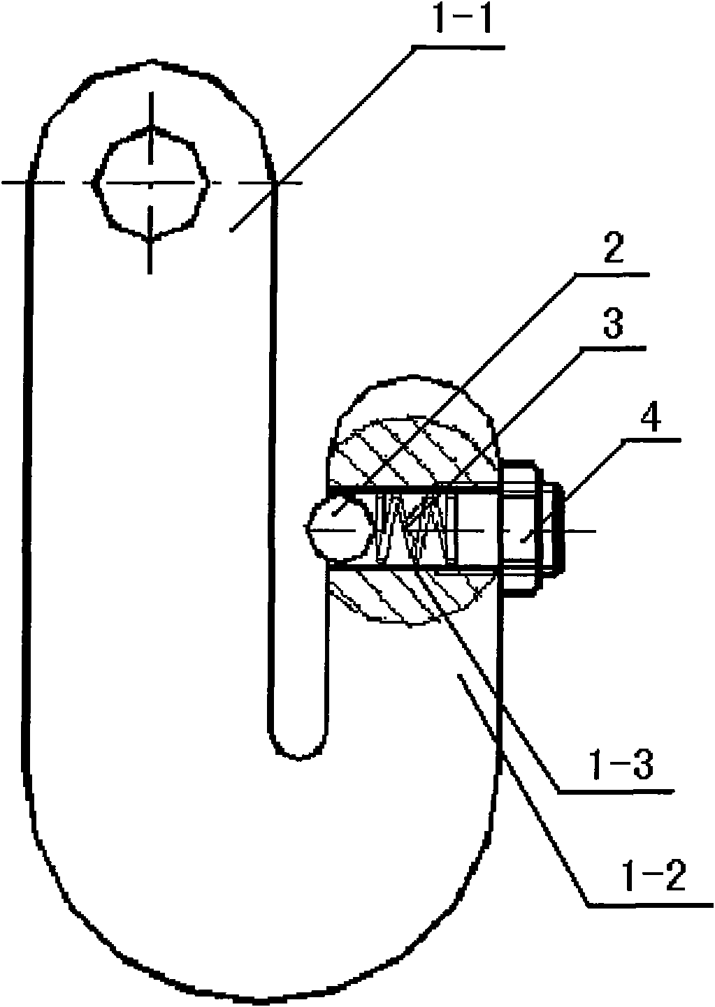
[0010] This self-locking hook as shown in the figure has a transverse groove 1-3 at the upper end of the auxiliary side hook body 1-2 of the hook main body 1-1, and a steel ball 2 and a spring 3 are housed in the transverse groove 1-3. The inner diameter of the transverse groove 1-3 is smaller than the ball diameter of the steel ball 2, so that the position of the steel ball is limited to the inside of the groove without dislocation. The adjusting bolt 4 is located outside the slot. The tension of the spring is adjusted by adjusting the bolt, so as to generate thrust on the steel ball.

[0011] When this kind of self-locking hook is in use, the operator (single person) puts the hook into the suspension ring from bottom to top, so that the inner hook bottom of the suspension hook contacts the suspension ring. At this moment, the steel ball 2 that is located on the main body 1-1 of the suspension hook is first squeezed into the groove, and the suspension hook and the suspension...


PUM


Abstract

The invention relates to a self-locking lifting hook, which has an unsymmetrical U shape consisting of a lifting hook main body (1-1) and a subsidiary side hook body (1-2), and is characterized in that a transverse groove (1-3) is arranged in the subsidiary side hook body (1-2), and an automatic elastic locking piece consisting of a steel ball (2), a spring (3) and an adjusting bolt (4) is arranged in the groove; and the inner side diameter of the transverse groove (1-3) is smaller than the ball diameter of the steel ball (2), and the adjusting bolt (4) is arranged on the outer side of the transverse groove (1-3) through a thread structure. The self-locking lifting hook not only has a simple structure, but also achieves the connection and the disconnection with a lifting hoisting ring through an elastic locking structure arranged on the subsidiary side hook body and avoids the common manual supports during the conventional lifting, so the self-locking lifting hook has very perfect utilization safety and reasonable use function.

Description

technical field [0001] The invention relates to a mechanical lifting device, in particular to a self-locking lifting hook. Background technique [0002] The hook is one of the common components of the lifting gear in the loading and unloading machinery. When in use, the hook is hooked on the ring of the object to be hung. Before the lifting equipment is lifted, the hook must be manually supported to prevent the hook from falling from the ring Otherwise, normal lifting tasks cannot be performed. It can be seen that this hook has structural defects, so its operation method not only increases the work difficulty of the hanger, but also holds the hook with one hand and controls the operating lever with one hand, which is very easy to cause safety accidents. If there are multiple hanging positions (rings) for a suspended part, additional operators need to be added to cooperate to complete the hanging task, which increases labor costs. Contents of the invention [0003] The pu...

Claims


Application Information

Patent Timeline
Patent Type & Authority Applications(China)
IPC IPC(8): B66C1/36
Inventor 沈建业张云峰
Owner 华宝资本有限公司
Why Eureka
Try Eureka