
Optical system of laser cloud meter

A technology for an optical system and a receiving optical system, which is used in radio wave measurement systems, instruments, measurement devices, etc., can solve the problems of large body weight, scattered structure, and large demand for lens elements, and achieves compact structure, low cost, and high solution. Spatially coherent effects

Active Publication Date: 2012-02-08
CAMA LUOYANG ENVIRONMENTAL MEASUREMENT
View PDF1 Cites 0 Cited by
  • Summary
  • Abstract
  • Description
  • Claims
  • Application Information

AI Technical Summary

Problems solved by technology

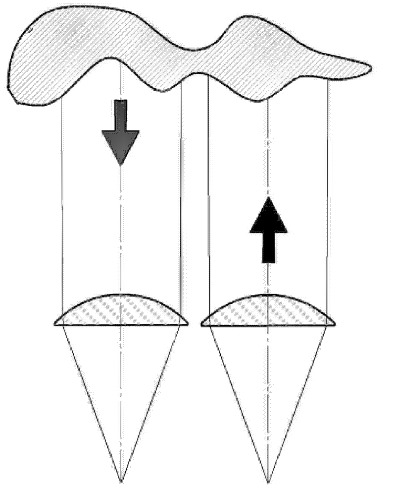
[0004] Existing laser nephelometry products mostly adopt the sending and receiving separate optical system with the optical axis of the emitting optical system and the optical axis of the receiving optical system separated and arranged in parallel. The layout of this scheme is as follows: figure 1 As shown, the transmitting optical system and the receiving optical system each have their own lenses, so two sets of lenses and two sets of structures are required, and the layout of this optical system has the disadvantages of scattered structure, heavy weight, and a large number of lens elements.

Method used


Image

  • Optical system of laser cloud meter
  • Optical system of laser cloud meter
  • Optical system of laser cloud meter

Examples


Embodiment Construction

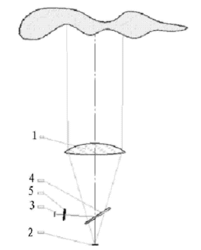
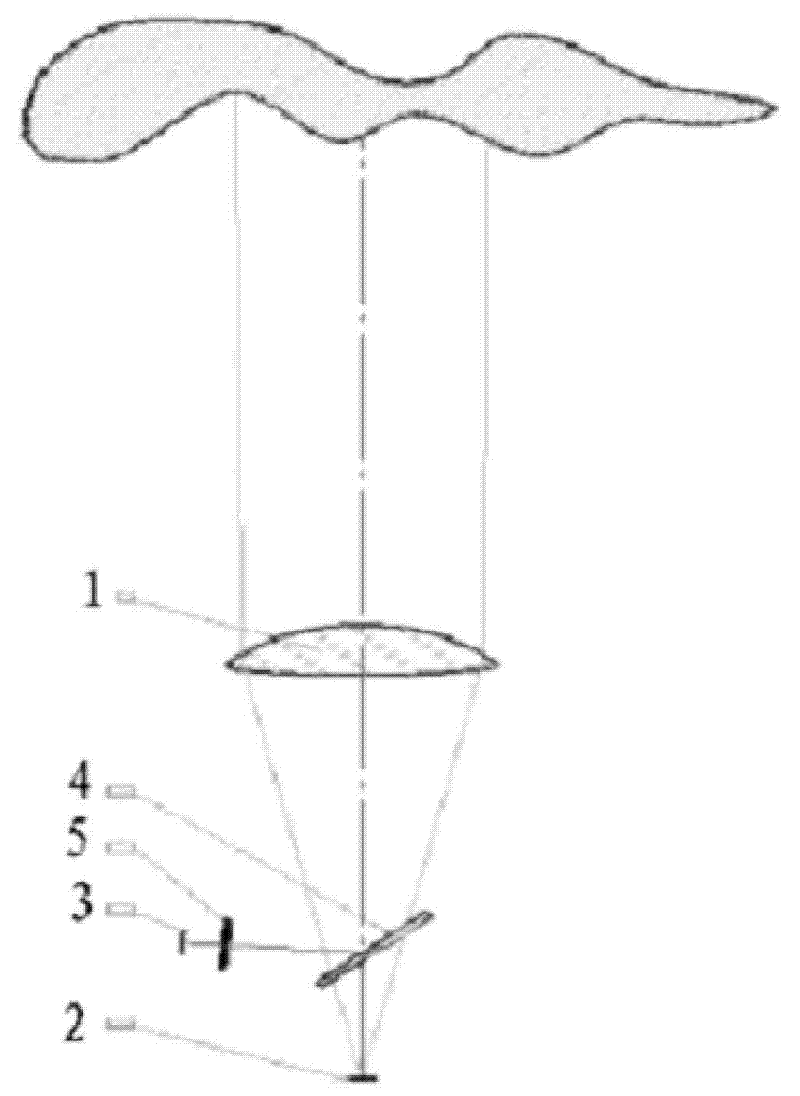
[0017] Alternative schemes for the overall layout of the optical system of the laser ceilometer, including "separation of sending and receiving" and "integration of sending and receiving". The so-called sending and receiving separation type means that the transmitting optical system and the receiving optical system have their own lenses, and the optical axis of the transmitting optical system and the optical axis of the receiving optical system are separated from each other and arranged in parallel, such as figure 1 shown. The so-called send-receive-in-one type, that is, the transmitting optical system and the receiving optical system share a set of lenses, the optical axis of the transmitting optical system and the optical axis of the receiving optical system overlap each other, and are only divided into two when they are close to the installation position of the device. ,Such as figure 2 shown.

[0018] The optical system of the laser nephelograph of the present invention...


PUM


Abstract

The invention relates to an optical system of a laser ceilometer, comprising a laser emitter, a laser receiver, an emitting optical system and a receiving optical system, wherein the emitting optical system and the receiving optical system share an optical lens, and a dichroic reflector is arranged between the optical lens and a focal plane positioned below the optical lens in an inclining way and is positioned on an optical axis of the optical lens; and the laser emitter and the laser receiver are respectively arranged on focal planes of the emitting optical system and the receiving optical system. The invention has the advantages of compact structure, small volume, light weight and low cost.

Description

technical field [0001] The invention relates to an optical system of a laser nephelograph. Background technique [0002] The laser cloud meter is an active photoelectric detection device that works at the laser wavelength. The device includes two optical components: a laser transmitter and a laser receiver. Each optical component is equipped with a set of optical systems, which are called the transmitting optical system and the receiving optical system. . The transmitting optical system is used to collimate the divergent beam radiated by the laser, and the receiving optical system is used to collect the laser echo signal scattered by the cloud. From the analysis of the principle of optical imaging, the "object" of the emitting optical system is the light-emitting surface of the laser radiation source, and the "image" formed by the "object" by the emitting optical system should be on the bottom of the cloud layer at infinity. Therefore, the "object" of the emitting optical s...

Claims


Application Information

Patent Timeline
Patent Type & Authority Patents(China)
IPC IPC(8): G01S7/481G01S17/95
CPCY02A90/10
Inventor 李春亮沙广军佟增亮滕军
Owner CAMA LUOYANG ENVIRONMENTAL MEASUREMENT
Learn More