
Combined structure of circuit carrier and transformer

A technology of transformers and circuits, which is applied in the direction of electrical component structure association, transformer/reactor installation/support/suspension, transformer/inductor coil/winding/connection, etc., which can solve the problem of shortening the electrical safety distance of transformers and reducing the safety of electronic devices , Electronic devices cannot meet the problems of thinning and miniaturization, so as to achieve the effect of reducing the overall thickness and improving safety

Active Publication Date: 2012-07-04
DELTA ELECTRONICS INC
View PDF6 Cites 0 Cited by
  • Summary
  • Abstract
  • Description
  • Claims
  • Application Information

AI Technical Summary

Problems solved by technology

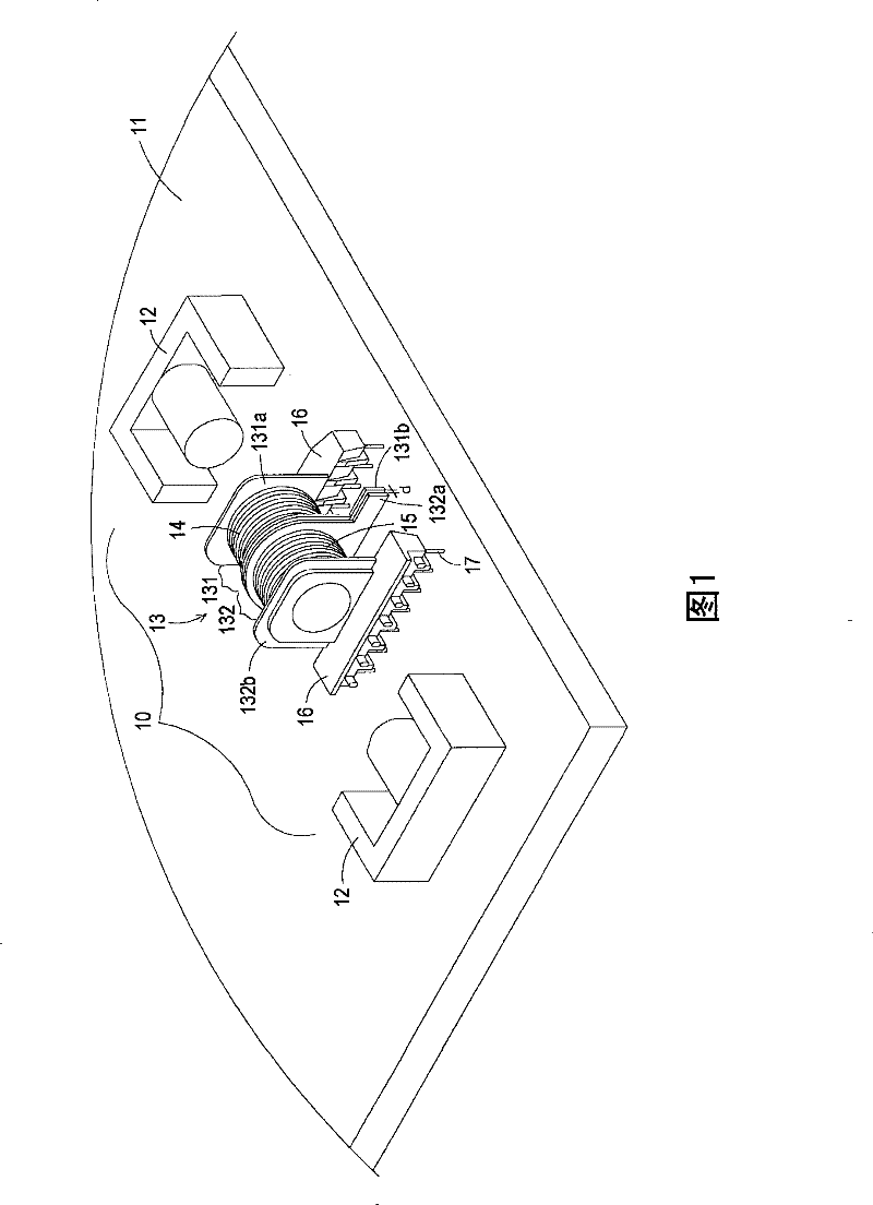
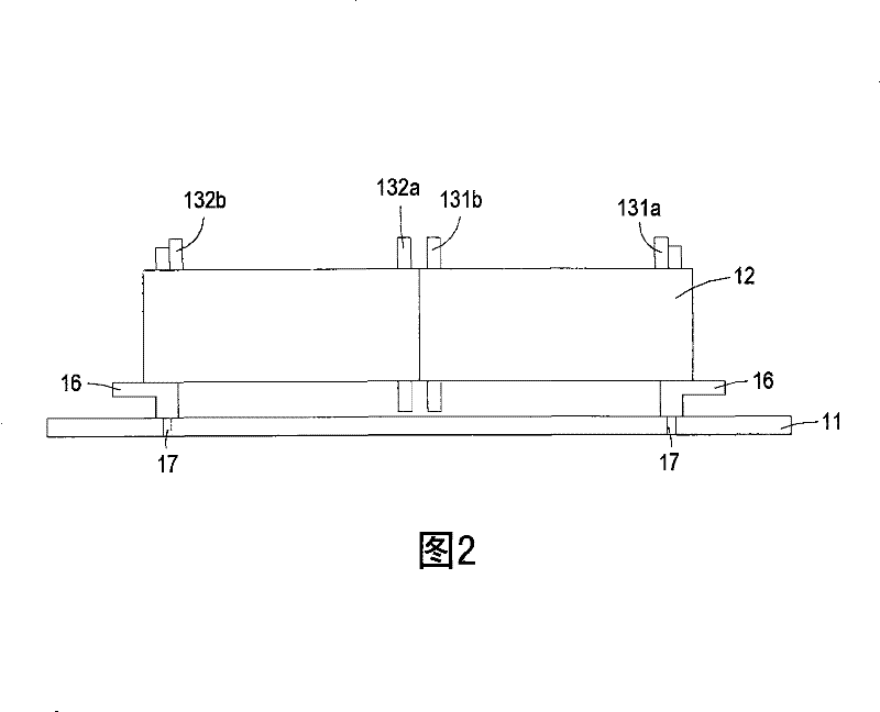
[0006] The main purpose of the present invention is to provide a combined structure of a circuit carrier and a transformer, which can solve the problem that the existing electronic device occupies more space due to the contact between the pin seat and the surface of the circuit carrier when the transformer is installed on the circuit carrier. A certain height makes the electronic device unable to meet the shortcomings of thinning and miniaturization, and when the transformer is arranged on the circuit carrier, it will be caused by the second side plate of the first winding part on the winding base and the second side plate. The third side plate of the winding part is too close to the circuit carrier, which shortens the electrical safety distance between the primary winding and the secondary winding of the transformer, thereby reducing the safety of the electronic device.

Method used


Image

  • Combined structure of circuit carrier and transformer
  • Combined structure of circuit carrier and transformer
  • Combined structure of circuit carrier and transformer

Examples


Embodiment Construction

[0033] Some typical embodiments embodying the features and advantages of the present invention will be described in detail in the description in the following paragraphs. It should be understood that the invention is capable of various changes in different embodiments without departing from the scope of the invention, and that the description and drawings therein are illustrative in nature and not limiting. this invention.

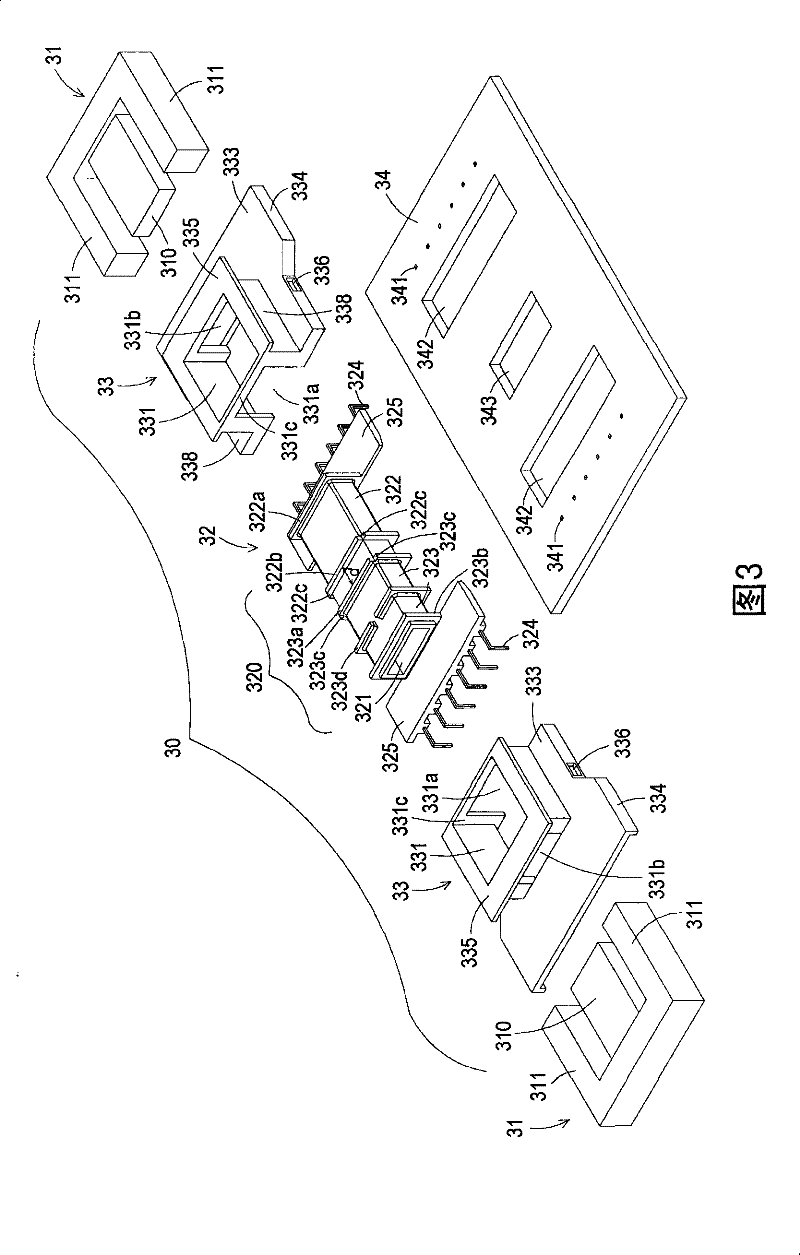
[0034] see Figure 3 to Figure 5 ,in image 3 It is a schematic diagram of the exploded structure of the circuit carrier and the transformer in the preferred embodiment of the present invention when they are not combined, and Figure 4 and Figure 5 respectively image 3 The front and back schematic diagrams of the combined structure of the transformer shown. Such as Figure 3 to Figure 5 As shown, the transformer 30 and the circuit carrier 34 of the present invention can be combined and disposed in an electronic device, and the electronic device can...


PUM


Abstract

The invention provides a combined structure of a circuit carrier and a transformer, which at least comprises the transformer and the circuit carrier, wherein the transformer is provided with a winding base which comprises a plurality of pin bases; and the circuit carrier is provided with a plurality of accommodation holes which are respectively arranged corresponding to the pin bases of the winding base, and is used for accommodating partial pin bases corresponding to the winding base when the transformer is arranged on the circuit carrier. When the transformer is arranged on the circuit carrier, the entire relative height can be reduced to meet the requirements of thin shape and minimization.

Description

technical field [0001] The present invention relates to a combined structure of a circuit carrier and a transformer, in particular to a structure that uses a plurality of accommodation holes on the circuit carrier to accommodate part of the transformer, so that the relative height of the transformer can be reduced when it is placed on the circuit carrier The combined structure of the circuit carrier and the transformer. Background technique [0002] An electronic device, such as a LCD TV, will have a circuit carrier inside it, such as a circuit board and a transformer. Applicable voltage range. [0003] see figure 1 , which is a schematic diagram of an exploded structure of an existing electronic device when the circuit carrier and the transformer are not yet combined. Such as figure 1 As shown, the circuit carrier 11 in the existing electronic device can be provided with a transformer 10, and the transformer 10 is used to convert voltage, and consists of a magnetic core...

Claims


Application Information

Patent Timeline
Patent Type & Authority Patents(China)
IPC IPC(8): H01F27/06H01F27/28H01F27/40
Inventor 陈义霖蔡辛卫李家庆陈诗云
Owner DELTA ELECTRONICS INC
Learn More