
Wall-through connection terminal board

A terminal block and terminal technology, applied in the direction of connection, conductive connection, electrical components, etc., can solve the problems of increasing the number of molds, prolonging the production cycle, increasing manufacturing costs and management costs, etc., to improve safety, avoid short circuits or The effect of igniting fire and strengthening firmness

Active Publication Date: 2010-01-27
CHENGDU RELIANCE ELECTRIC
View PDF0 Cites 7 Cited by
  • Summary
  • Abstract
  • Description
  • Claims
  • Application Information

AI Technical Summary

Problems solved by technology

The existing through-wall terminal block adopts two combined technologies: one is to open a through hole on each terminal block, and then use a longer bolt to pass through the hole to connect multiple terminal blocks into one , and finally fix it with nuts at the tail, because in actual use, the combination length of the through-wall terminal block is diverse, and there are many length specifications, resulting in too many bolt specifications, increased processing difficulty, and high manufacturing and management costs. Improvement; another combination technology is to directly inject multiple pieces of terminal blocks into a whole. This structure reduces the flexibility of the product in terms of length adaptation. Different length specifications require different molding molds, which greatly increases the mold. The quantity, not only prolongs the production cycle, but also increases the manufacturing cost
At the same time, the wall-through terminal block in the prior art is not equipped with protective devices, and dust, foreign objects, etc. are easy to fall on the conductive parts of the terminal block, increasing the risk of short circuit and fire

Method used


Image

  • Wall-through connection terminal board
  • Wall-through connection terminal board
  • Wall-through connection terminal board

Examples


Embodiment approach

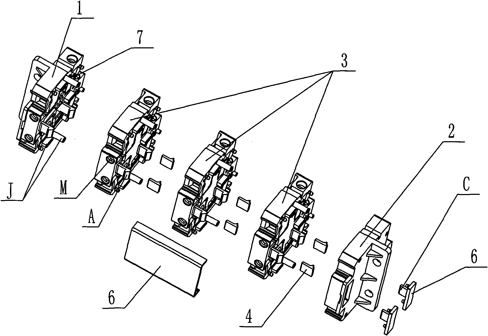
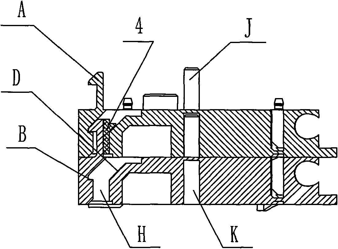
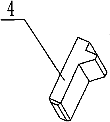
[0021] like Figure 1-2 As shown, the first specific embodiment of the present invention is: a through-wall terminal block, which is composed of a front end plate 1, a rear end plate 2 and a plurality of terminal blocks 3. In this embodiment, a total of Three pieces of terminal blocks 3 with the same structure, in actual use, any number of terminal blocks 3 can be set as required, protruding hooks A are arranged on the front panel 1 and the front of each terminal block 3, the hooks A is L-shaped; on the back of the rear end plate 2 and each piece of terminal block 3, a connecting hole H corresponding to the hook A is provided, and on the side wall of the connecting hole H, a matching hook A is provided. Hanging table B, hanging table B is a concave table surface sunken in the wall of the connecting hole H, the hook A of the front plate 1 can be buckled on the hanging table B of the adjacent terminal block 3; the hook A of each terminal block 3 Can be buckled on the hanging pl...


PUM


Abstract

The invention discloses a wall-through connection terminal board comprising a front end plate (1), a rear end plate (2) and a plurality of connection terminal blocks (3). The front faces of the front end plate (1) and each connection terminal block (3) are provided with raised L-shaped hooks (A); the back faces of the rear end plate 92) and each connection terminal block (3) are provided with connecting holes (H) corresponding to the hooks (A); one side wall of each connecting hole (H) is provided with a hanging platform (B) matched with each hook (A); and the front end plate or the hook (A) of a former connection terminal block can be buckled on the hanging platform (B) of the next connection terminal block or the rear end plate. By adopting the buckling mode, the connection terminal blocks (3) can be combined and spliced to achieve any length without being limited by the amount so that the wall-through connection terminal board can flexibly realize any length and is convenient to use. Meanwhile, the wall-through connecting terminal board is also provided with a protection cover (6) which can prevent dust and foreign matters from intruding and improve the security of the wall-through connecting terminal board.

Description

technical field [0001] The invention relates to a low-voltage switchgear, control equipment and auxiliary electrical appliances for relay protection equipment, in particular to a through-wall terminal block used in the field of relay protection. Background technique [0002] In the fields of low-voltage electrical appliances, relay protection industry and industrial automation, the through-wall terminal block installed on the electrical control cabinet and relay protection screen panel has been more and more widely used because of its convenient wiring and reliable performance. The application of this kind of products is composed of multiple terminal blocks into a whole. It is necessary to determine the number of terminal blocks first, and then connect the multiple terminal blocks into one body through various combination techniques to facilitate installation into the cabinet. or on the panel of the housing. The existing through-wall terminal block adopts two combined techn...

Claims


Application Information

Patent Timeline
IPC IPC(8): H01R9/00H01R9/22
Inventor 李强
Owner CHENGDU RELIANCE ELECTRIC
Learn More