Pre-positioning liquid cooling permanent-magnetic retarder for gear box

A technology of gearbox and retarder, applied in the field of front-mounted liquid-cooled permanent magnet retarder of gearbox, can solve the problems of rotor drum temperature rise, magnetic leakage torque, low working reliability, etc., and achieve enhanced braking effect, the overall structure is compact, the heat dissipation effect is good

Inactive Publication Date: 2010-01-27
北京齿轮总厂 +1
View PDF0 Cites 17 Cited by
  • Summary
  • Abstract
  • Description
  • Claims
  • Application Information

AI Technical Summary

Problems solved by technology

These permanent magnet retarder structures are all installed on the output shaft of the gearbox or the rear axle. When the vehicle brakes, the retarder needs to generate a large braking torque to achieve the purpose of braking; their stators are equipped with permanent magnets. The bracket, the rotor with helical teeth rotates outside the stator, and achieves heat dissipation through air cooling. These structures have poor heat dissipation effects. When braking for a long time, the temperature of the rotor drum rises, and the braking effect decreases significantly; and all of them are through rotation or movement. Permanent magnets are used to achieve the purpose of controlling the magnetic circuit. This control method not only makes the structure of the permanent magnet retarder complex, the work reliability is low, and there is a magnetic leakage torque when it is not braking.

Method used


Image

  • Pre-positioning liquid cooling permanent-magnetic retarder for gear box

Examples


Embodiment Construction

[0015] Further illustrate the present invention below in conjunction with accompanying drawing.

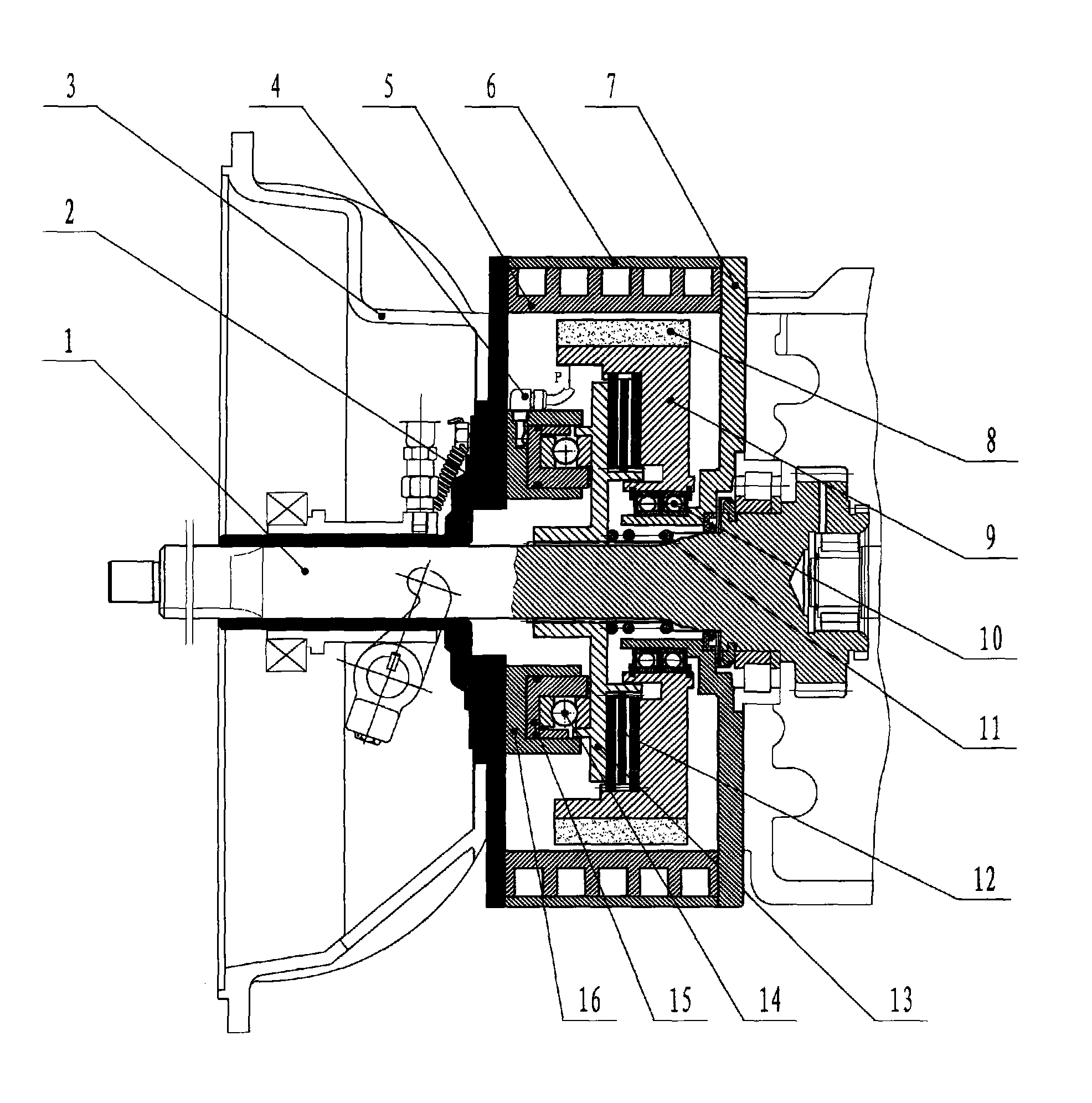
[0016] like figure 1 , the clutch end cover 2 is connected with the clutch housing 3 through bolts, the transmission end cover 7 is connected with the transmission case through bolts, the retarder stator drum 5 is installed between the clutch end cover 2 and the transmission end cover 7, and the water channel is sealed The cover 6 and the water channel on the stator drum 5 form a liquid cooling device. The permanent magnets 8 are evenly distributed on the magnet holder 9 along the circumference, and the magnet holder 9 is connected with the gearbox end cover 7 through the bearing 10 and can rotate freely, keeping a certain gap with the stator drum. The control mechanism is made up of a cylinder 16, a piston 15, a clutch disc 13, a thrust bearing 14, a friction plate 12 and a return spring 11, and the cylinder 16 is fastened on the clutch end cover 2 by bolts. The piston 15 is se...


PUM


Abstract

The invention relates to a permanent-magnetic retarder. The structure of the retarder comprises a stator, a rotor and a control mechanism. The rotor consists of a plurality of permanent magnets and a magnet retainer, and can be rotationally arranged in the stator. The control mechanism is positioned inside the rotor and used for operating and controlling the braking state. The permanent-magnetic retarder is arranged between an automobile clutch and a gear box, and the braking effect of the retarder on an automobile is enhanced through the speed reducing function (namely torque amplification) of the gear box; the stator of the permanent-magnetic retarder is arranged on the outer side of the rotor, and a rotating part is arranged inside the rotor, so the permanent-magnetic retarder is safer compared with the prior permanent-magnetic retarder or the current vortex retarder; the stator of the permanent-magnetic retarder is provided with a liquid cooling device so that the heat dissipation effect is good, and the brake torque does not decline when the permanent-magnetic retarder works for a long time; the control mechanism of the permanent-magnetic retarder adopts the prior frictional plate type, so the shift of the braking state can be easily realized, and no magnetic leakage torque is generated in the non-braking period; and the permanent-magnetic retarder has the advantages of compact integral structure and small volume and mass.

Description

technical field [0001] The invention uses NdFeB permanent magnets as the eddy current braking magnetic source, through the reverse eddy current braking force generated in the rotation and non-contact, to decelerate the auxiliary braking device for the vehicle, especially a kind of auxiliary braking device placed at the front end of the gearbox liquid-cooled permanent magnet retarder. Background technique [0002] The retarder is a safety auxiliary device for driving brakes, which applies the braking force to the transmission parts of the vehicle to reduce the driving speed of the vehicle. At present, the retarders commonly used at home and abroad mainly include hydraulic retarders and electric eddy current retarders. Although their working principles are different, as an auxiliary braking device, their effects are obvious. The permanent magnet type retarder uses its own permanent magnet to form a magnetic field to play a retarding role, so there is almost no power consumpti...

Claims


Application Information

Patent Timeline
Patent Type & Authority Applications(China)
IPC IPC(8): H02K49/04B60T1/00
Inventor 马元京李德胜叶乐志马岳北周宜莉王文武
Owner 北京齿轮总厂
Why Eureka
Try Eureka