Control method for panoramically aerial camera photographing signals

A control method, aerial camera technology, applied in the direction of image communication, color TV parts, TV system parts, etc., can solve the problem of difficult to ensure the overlapping rate of indicators

Inactive Publication Date: 2010-01-27
CHANGCHUN INST OF OPTICS FINE MECHANICS & PHYSICS CHINESE ACAD OF SCI
View PDF0 Cites 9 Cited by
  • Summary
  • Abstract
  • Description
  • Claims
  • Application Information

AI Technical Summary

Problems solved by technology

However, because the camera is disturbed by the aircraft roll angular velocity and the size of the aircraft window during the photographing process, it is difficult to control the position / speed signal and photographic pulse signal based on the position information of the lens barrel to meet the requirements of the index overlap rate.

Method used


Image

  • Control method for panoramically aerial camera photographing signals
  • Control method for panoramically aerial camera photographing signals
  • Control method for panoramically aerial camera photographing signals

Examples


Embodiment Construction

[0048] 1. The camera controller system uses the latest digital signal processing unit (TMS320F2812) from Texas Instruments (TI) as the main controller. It has high-speed computing capabilities, and its characteristics are: 50MHz operating frequency, 32-bit data lines, 18kRAM, 128kFLASH, 16 Channel PWM, 3 timers, 2 full-duplex SCI serial ports. The camera controller system and the lens barrel system exchange data through the RS-422 serial port, and DS26C31 and DS26C32 are selected as the RS-422 serial communication interface chips.

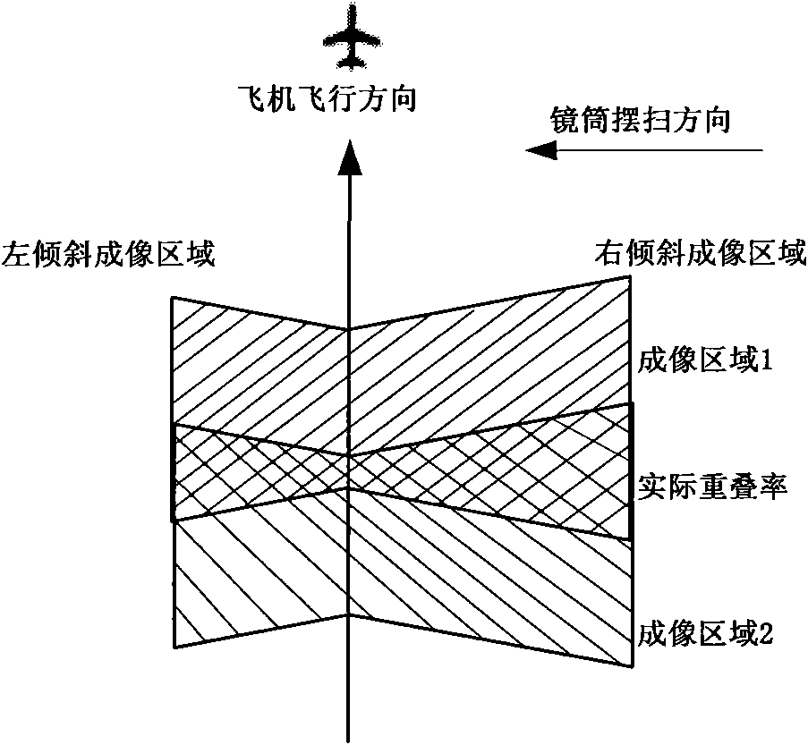
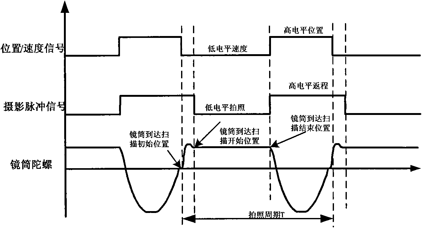
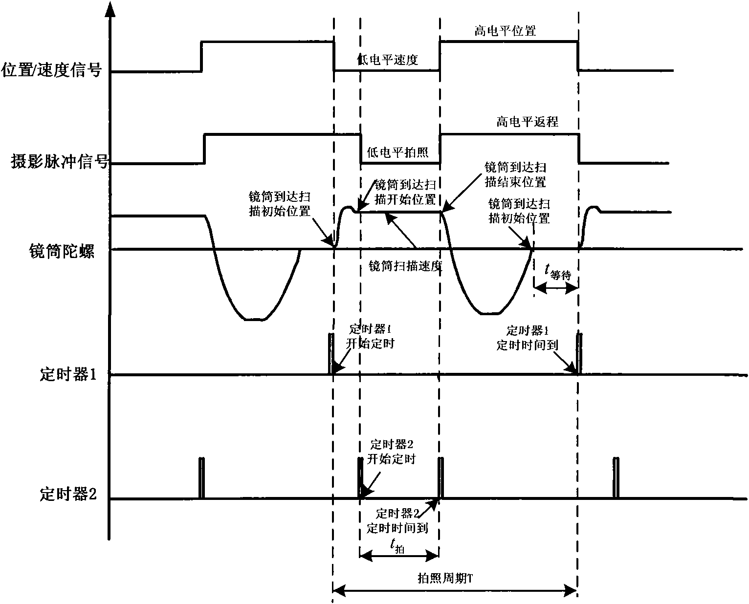
[0049] 2. The camera controller system calculates the camera lateral scan angle 2β according to the current camera speed-to-height ratio and index overlap rate according to formula (1), and then determines the initial scanning position of the lens barrel, the scanning start position and Scanning end position, lens barrel photographing time t 拍 and lens barrel photographing period T. The camera controller system sends these five working parameters...


PUM


Abstract

A control method for panoramically aerial camera photographing signals belongs to the aerial camera measuring and imaging technology control field. According to velocity-height ratio, index overlapping coefficient, target slant angle and roll angle of an airplane at the current moment, a cameral controller figures out the scanning initial position, the scanning beginning position, the scanning ending position, the photographing time t photographing and the photographing period T of a lens cone which serve as working parameters to be sent into a lens cone system. The lens cone system controls timing sequence sending position/ speed signals and photographing pulse signals at the scanning initial position according to photographing signals. Finally, after receiving the position/speed signals and the photographing pulse signals sent by the lens cone system, a reflector conducts image motion compensation, a focusing system automatically focus, and a roll system conducts roll compensation; therefore, all systems finish the consistency of the functional timing sequence in the he photographing time and the requirement of the camera meeting the index overlapping coefficient is guaranteed.

Description

technical field [0001] The invention relates to a method for controlling a photographing signal of a panoramic aerial camera, which belongs to the technical field of aerial camera measurement and imaging, and is especially aimed at the imaging of a panoramic aerial camera. technical background [0002] The panoramic aerial camera adopts the working method of lens barrel swinging. When the camera is taking pictures, it will image a designated strip area on the ground; when returning, it will not image. The larger the scanning angle of the aerial camera, the wider the ground coverage width, and the longer the photographing cycle. There may be gaps between two adjacent images, resulting in the loss of image information. Therefore, in order to make the captured images continuous and seamless, it is required to maintain a certain index overlap rate in the strip regions of two adjacent imagings. At present, the panoramic aerial camera uses the camera signal to control the time o...

Claims


Application Information

Patent Timeline
Patent Type & Authority Applications(China)
IPC IPC(8): H04N5/238
Inventor 张雪菲匡海鹏陈志超刘志明王德江
Owner CHANGCHUN INST OF OPTICS FINE MECHANICS & PHYSICS CHINESE ACAD OF SCI
Why Eureka
Try Eureka