

Quick charging method of lithium based secondary battery and electronic apparatus employing it
A technology for secondary batteries and electronic equipment, applied in secondary battery charging/discharging, secondary batteries, secondary battery repair/maintenance, etc., can solve problems such as shortening charging time, and achieve the effect of preventing overcharging and fast charging
- Summary
- Abstract
- Description
- Claims
- Application Information
AI Technical Summary
Problems solved by technology
Method used
Image

Examples
Embodiment 1
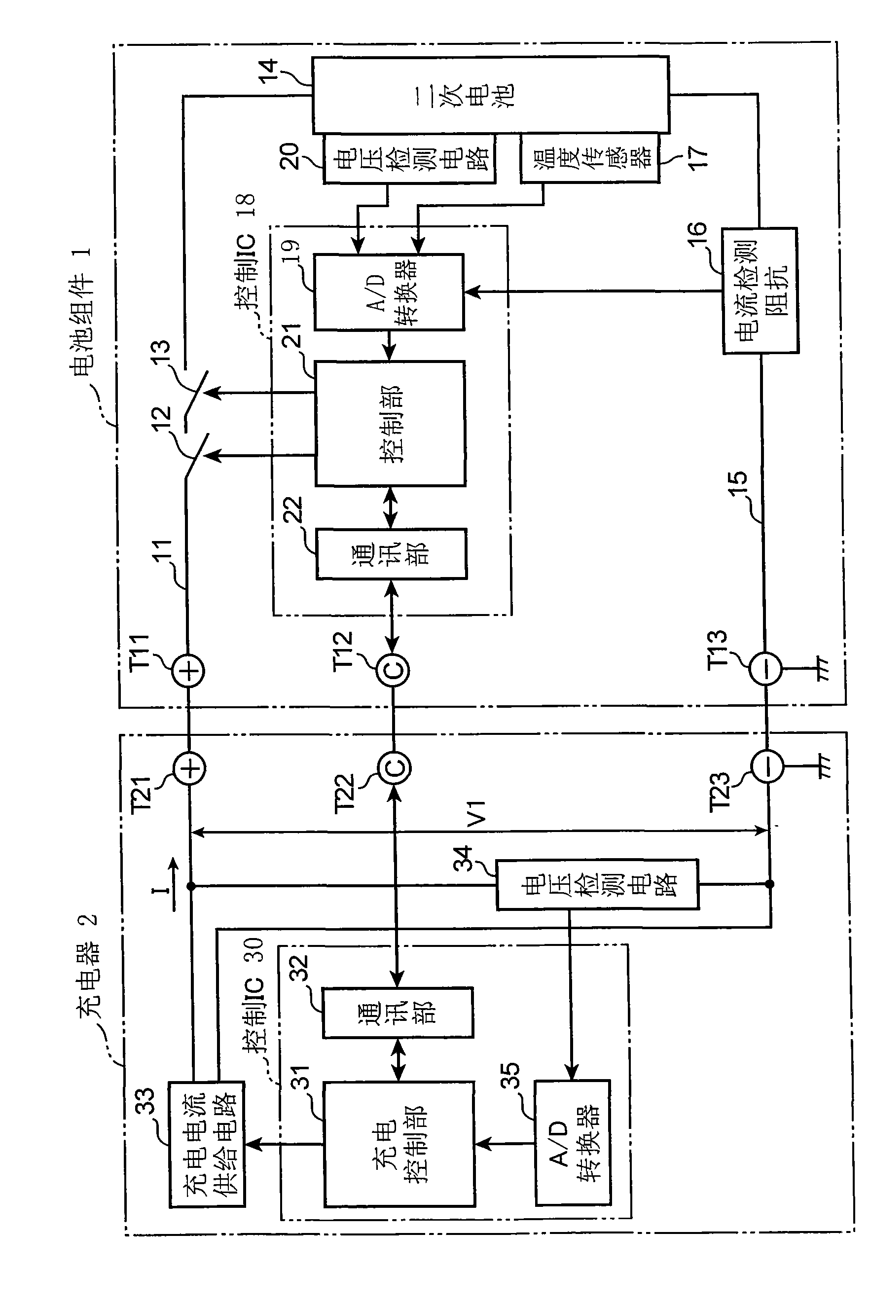
[0025] figure 1 It is a block diagram showing the electrical configuration of the electronic device according to Embodiment 1 of the present invention. This electronic device includes a battery pack 1, a charger 2 for charging the battery pack, and a load device not shown. exist figure 1 Although the battery pack 1 is charged by the charger 2, the battery pack 1 may be mounted on the above-mentioned load device and charged by the load device. The battery pack 1 and the charger 2 are connected to each other through DC high-side terminals T11, T21 for power supply, communication signal terminals T12, T22, and GND terminals T13, T23 for power supply and communication signals. Even in the case where the above-mentioned load device is provided, the same terminals are provided.
[0026] In the battery pack 1, FETs 12 and 13 having different conduction forms for charging and discharging are interposed in a DC high-side charge-discharge path 11 extending from the terminal T11, an...
Embodiment 2
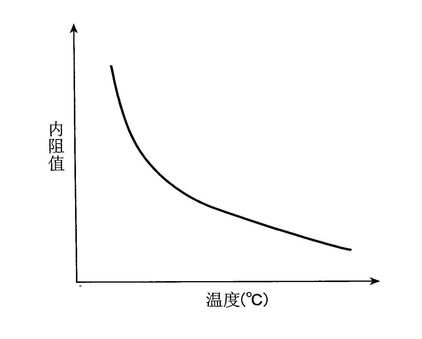
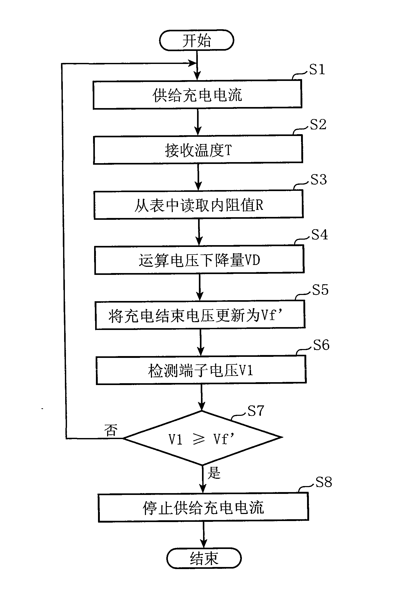
[0044] Figure 5 It is a flowchart for describing in detail the charging operation in the electronic device according to the second embodiment of the present invention. In this example, the above-mentioned figure 1 structure of the electronic device shown in the Figure 5 processing, for the above image 3 Similar or corresponding parts of the processing are denoted by attaching the same step numbers, and descriptions thereof are omitted. It should be noted that, in this embodiment, not only the internal resistance value R but also the terminal voltage V1 and the actual capacity W of the secondary battery 14 are taken into consideration to determine the end-of-charge voltage Vf'. The above internal resistance value R(DC-IR) is not only as figure 2 As shown, the higher the temperature becomes smaller, and as Image 6 As shown, it will change according to SOC (State of Charge). Furthermore, if the deterioration increases due to repeated charging and discharging, the inte...
Embodiment 3
[0053] Figure 8 It is a block diagram showing an example of the configuration of an electronic device according to Embodiment 3 of the present invention. exist Figure 8 in, right with figure 1 The electronic devices shown have the same configurations and are given the same symbols, and descriptions thereof are omitted. Figure 8 The electronic equipment shown is compatible with figure 1 The illustrated electronic devices differ in the following respects. That is, in Figure 8 In the illustrated electronic device, the control unit 21 a functions as the charge control unit 210 , the internal resistance estimation unit 211 , and the end voltage calculation unit 212 .
[0054]Furthermore, the charging control unit 31a does not perform detection of the internal resistance value R, setting of the charging end voltage, or determination of whether or not charging has been completed. Moreover, the load device 4 is connected between the terminal T21 and the terminal T23. Furt...
PUM
| Property | Measurement | Unit |
|---|---|---|
| Particle size | aaaaa | aaaaa |
| Thickness | aaaaa | aaaaa |
Abstract
Description
Claims
Application Information