Multi-formation fracturing device and process of release tubular column

A fracturing and pipe string technology is applied in the field of multi-layer fracturing devices for lost-hand pipe strings. , to avoid the effect of sticking

Inactive Publication Date: 2010-02-03
CNPC SICHUAN GASOLINEEUM GEOPHYSICAL PROSPECTING ENG TECH RES INST
View PDF0 Cites 20 Cited by
  • Summary
  • Abstract
  • Description
  • Claims
  • Application Information

AI Technical Summary

Problems solved by technology

For the fracturing of small-hole and horizontal wells, the risk of downhole ...

Method used


Image

  • Multi-formation fracturing device and process of release tubular column

Examples


Embodiment 1

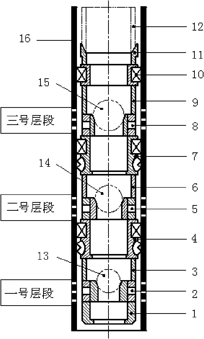
[0032] Example 1 provides an example of fracturing in three layers in a fracturing string.

[0033] Such as figure 1 As shown, it includes sliding sleeve seat 1, first-stage sand blaster 2, first-stage oil pipe 3, first-stage packer 4, second-stage sand blaster 5, second-stage oil pipe 6, and second-stage packing 7, the third-stage sand blaster 8, the third-stage oil pipe 9, the third-stage packer 10, the hand-off joint 11, and the oil delivery pipe 12. The first-stage sand blaster 2 is threadedly connected with the lowermost sliding sleeve seat 1, and is seated on the sliding sleeve seat 1; the first-stage sand blaster 2 connects with the first-stage packer 4 through the first-stage oil pipe 3 in the middle The connection forms a one-layer fracturing string. The second-stage sand blaster 5 is connected with the first-stage packer 4 through threads, and is seated on the first-stage packer 4. The second-stage sand blaster 5 passes through the second-stage oil pipe 6 and conne...

Embodiment 2

[0047] Embodiment 2 gives an embodiment in which the fracturing string has four layers.

[0048] Same as Example 1, at least including sliding sleeve seat 1, first-stage sand blaster 2, first-stage oil pipe 3, first-stage packer 4, second-stage sand blaster 5, second-stage oil pipe 6, first-stage Secondary packer 7, third-stage sand blaster 8, third-stage oil pipe 9, third-stage packer 10, hand-off joint 11, and oil delivery pipe 12. Add the fourth sand blaster, the fourth tubing, and the fourth packer on the basis of the above, and the first-stage sand blaster 2 is threadedly connected with the lowermost sliding sleeve seat 1 and is seated on the sliding sleeve seat 1; The first-stage sand blaster 2 is connected with the first-stage packer 4 through the intermediate first-stage tubing 3 to form a layer of fracturing string. The second-stage sand blaster 5 is connected with the first-stage packer 4 through threads, and is seated on the first-stage packer 4. The second-stage s...


PUM


Abstract

The invention relates to a multi-formation fracturing technology of oil, oil wells of gas fields, gas wells or water injection wells, in particular to a multi-formation fracturing device and a process of a release tubular column. The device at least comprises a sliding sleeve seat, a sand ejector, a stage oil pipe, packers, a release joint and an oil conveying pipe, wherein the sand ejector is connected with the sliding sleeve seat through threads and positioned on the sliding sleeve seat; the sand ejector is also connected with the packers through an oil pipe in the middle to form a layer offracturing tubular columns; the packer of the tubular columns on a front layer and the packer of the tubular columns on a rear layer are connected through threads and positioned on the packer of a forward stage; and the packer of a backward stage is connected with the release joint and then connected with the oil conveying pipe through the release joint. The process flow of the invention is completed through eleven steps, thereby realizing the continuous fracturing operations of multiple oil and gas formations of a slim hole and a horizontal well.

Description

technical field [0001] The present invention relates to the process technology of multi-stage fracturing of oil wells, gas wells or water injection wells in oil and gas fields, more precisely, it relates to the multi-stage fracturing device and process of the hands-off pipe string. Background technique [0002] Multi-stage fracturing technologies at home and abroad mainly include liquid plug fracturing, flow-limiting fracturing, nylon ball fracturing, hydraulic jet fracturing and mechanical tool fracturing. There are many procedures for liquid rubber plugs, which will cause certain damage to the reservoir; current limiting and nylon ball fracturing require good interlayer separation, and the construction is not easy to control; the hydraulic jet sand ratio is low, the water consumption is large, and the fracture creation effect needs to be evaluated . For mechanical tool isolation multi-stage fracturing, due to the small diameter of the small hole well, only small-sized tub...

Claims


Application Information

Patent Timeline
IPC IPC(8): E21B43/26E21B17/06
Inventor 张承武任雁鹏郑维师陈建刚
Owner CNPC SICHUAN GASOLINEEUM GEOPHYSICAL PROSPECTING ENG TECH RES INST
Why Eureka
Try Eureka