Piston-type hydro-pneumatic buffer

A liquid-gas buffer and piston-type technology, applied in the direction of gas-liquid shock absorbers, etc., can solve the problems of short maintenance period, high energy consumption, poor sealing performance, etc., reduce the difficulty of sealing and improve the ability to block oil leakage , Play the effect of working performance

Inactive Publication Date: 2010-02-03
深圳市业成实业有限公司
View PDF0 Cites 26 Cited by
  • Summary
  • Abstract
  • Description
  • Claims
  • Application Information

AI Technical Summary

Problems solved by technology

[0011] 2. It consumes a lot of energy. When the stroke is the same, the liquid-air buffer dissipates and absorbs the most energy
[0015] This kind of buffer has attracted much attention because of its advantages, but it has great disadvantages: poor sealing performance, oil leakage and air leakage
Therefore, its maintenance cycle is very short in use, and it has become a "super vulnerable part".

Method used


Image

  • Piston-type hydro-pneumatic buffer
  • Piston-type hydro-pneumatic buffer
  • Piston-type hydro-pneumatic buffer

Examples


Embodiment Construction

[0028] The embodiments will be described in detail below in conjunction with the accompanying drawings, through which the concept of the present invention can be more clearly understood.

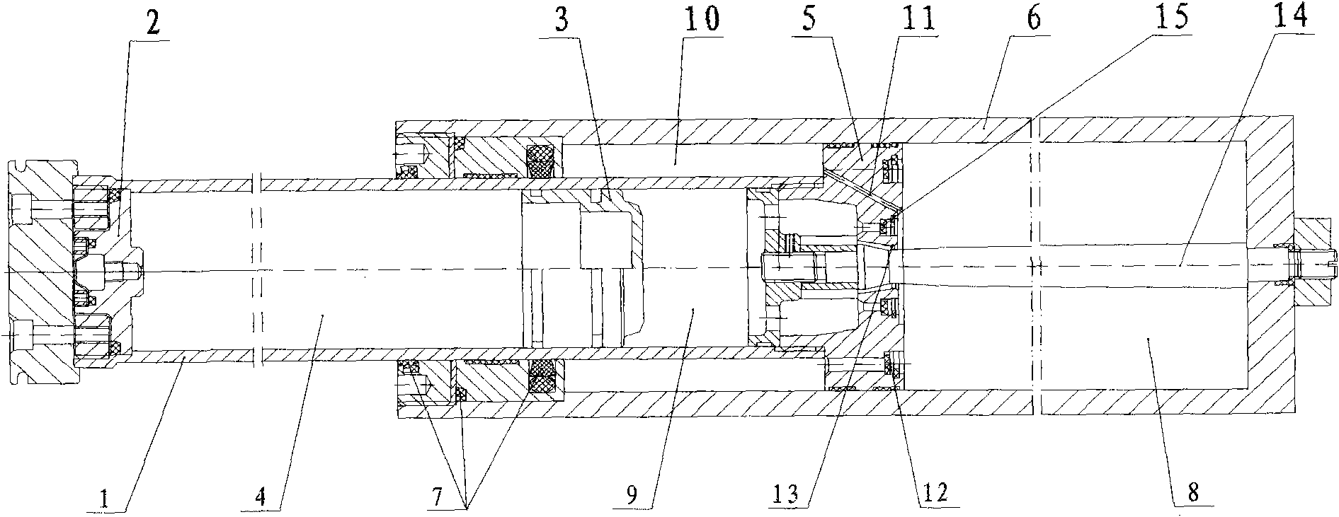
[0029] figure 2 It is a structural schematic diagram of an embodiment of the present invention.

[0030] In the piston-type liquid-gas buffer of this embodiment, 1 is a hollow piston rod, and an air-tight device 2 is provided at one end of the piston rod, and 3 is a floating piston arranged in the piston rod, which can slide along the inner wall of the piston rod. Between the piston and the air-tight device 2 is an air chamber 4, which is filled with compressed gas. The suitable gas used in this example is nitrogen, and the pressure of nitrogen in this example is 0.5-1 MPa; 5 is the other end of the piston rod The piston provided at the place, the second oil chamber 9 is formed between the piston 5 and the floating piston in the piston rod, and the piston 5 has an oil cylinder 6 which is a...


PUM


Abstract

The invention relates to a piston-type hydro-pneumatic buffer. A piston rod (1) is internally provided with a floating piston (3); an airtight device (2) and a piston (5) are respectively arranged atboth ends of the piston rod (1); a pressed air cavity (4) and a second oil cavity (9) are respectively arranged at both sides of the floating piston (3); a first oil cavity (8) is formed between the floating piston (3) and an oil cylinder (6) outside the floating piston (3); a first throttling passage and a second one-way valve (15) which is formed from the second oil cavity (9) to the first oil cavity (8) are arranged between the first oil cavity (8) and the second oil cavity (9); an oil seal (7) is arranged between the opening end of the oil cylinder (6) and the piston rod (1); a third oil cavity (10) is formed between the exterior of the piston rod (1) and the inner wall of the oil cylinder (6); and a second throttling passage (11) communicated with the first oil cavity and the third oil cavity and a first one-way valve (12) which is formed from the third oil cavity (10) to the first oil cavity (8) and is a passage larger than the second throttling passage (11) are arranged on the piston (5). The piston-type hydro-pneumatic buffer is provided with the low-pressure third oil cavity so that the oil seal has remarkable leakproof effect and fully exerts the advantages of the piston-type hydro-pneumatic buffer.

Description

technical field [0001] The present invention relates to a buffer, more specifically, to a piston type liquid-gas buffer. Background technique [0002] A variety of mobile machinery, such as: cranes used in ports and construction sites, vehicles on railways, rolling mills in the metallurgical industry, and elevators in high-rise buildings, are difficult to avoid collisions during work. In order to avoid the resulting huge load, affecting the normal operation of the machine, or even causing damage to the machine parts, buffers are generally installed. [0003] Currently widely used buffers are: [0004] ·Rubber / polyurethane buffers, [0005] Spring buffer with dry friction, [0006] · Hydraulic shock absorber with spring, [0007] ·Elastic clay buffer, [0008] · Liquid gas buffer. [0009] Among these buffers, liquid-air buffers perform best, namely: [0010] 1. Large capacity, when the stroke is the same, the impact energy absorbed by the liquid-pneumatic buffer is th...

Claims


Application Information

Patent Timeline
Patent Type & Authority Applications(China)
IPC IPC(8): F16F9/06
Inventor 吕再昌吴旭陈虎刘广彬唐俊杰
Owner 深圳市业成实业有限公司
Why Eureka
Try Eureka