Composite plate assembly

A technology of composite panels and assemblies, applied in the direction of sheet/board, thin panel connection, building components, etc., can solve the problems of long construction time, inconvenience, and program delay in assembly operations.

Inactive Publication Date: 2010-02-03
XXENTRIA TECH MATERIALS CO LTD
View PDF0 Cites 4 Cited by
  • Summary
  • Abstract
  • Description
  • Claims
  • Application Information

AI Technical Summary

Problems solved by technology

[0004] Therefore, since this type of composite board 1 is simply spliced ​​by means of gluing, there are doubts about the weak structural strength of the assembly. In particular, there must be a period of rest for the glue to cure, which can range from a few hours to a long time. For a f

Method used


Image

  • Composite plate assembly
  • Composite plate assembly
  • Composite plate assembly

Examples


Embodiment Construction

[0014] Below in conjunction with accompanying drawing and embodiment the present invention is described in detail:

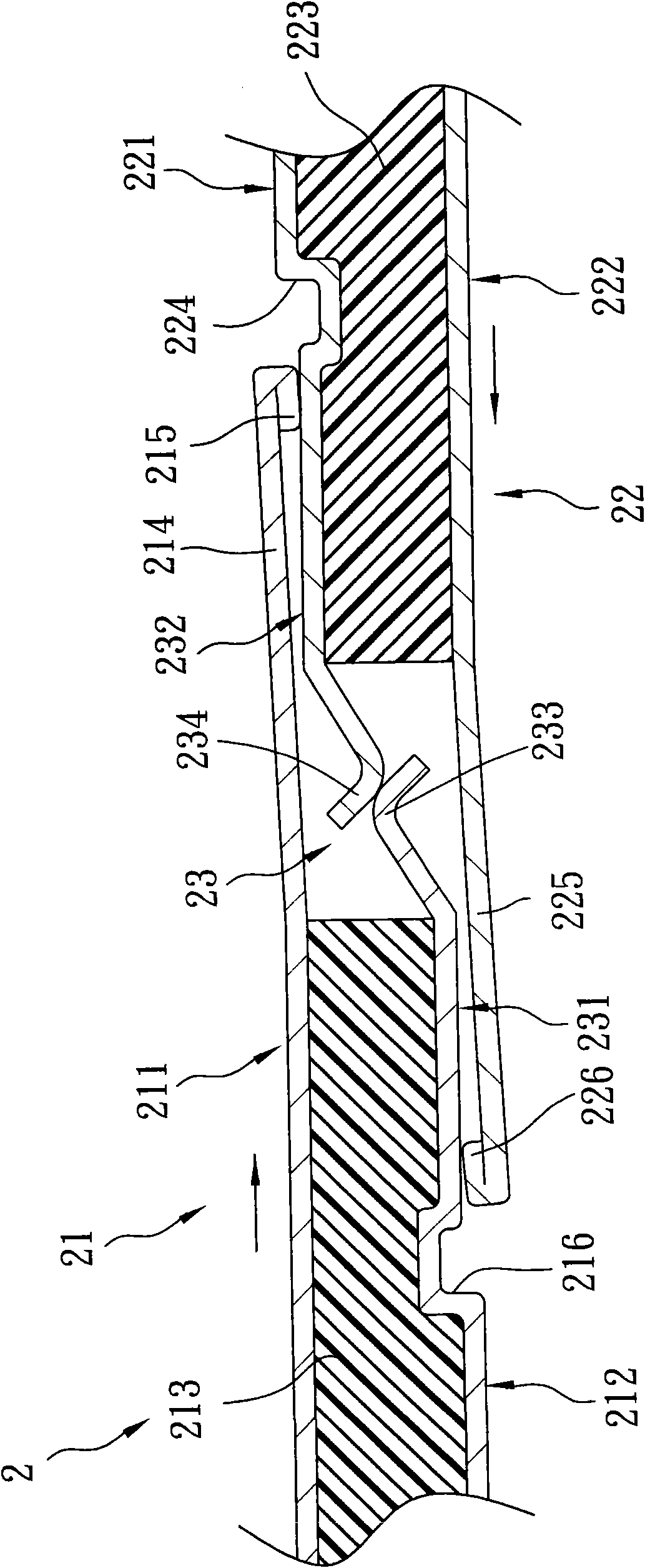
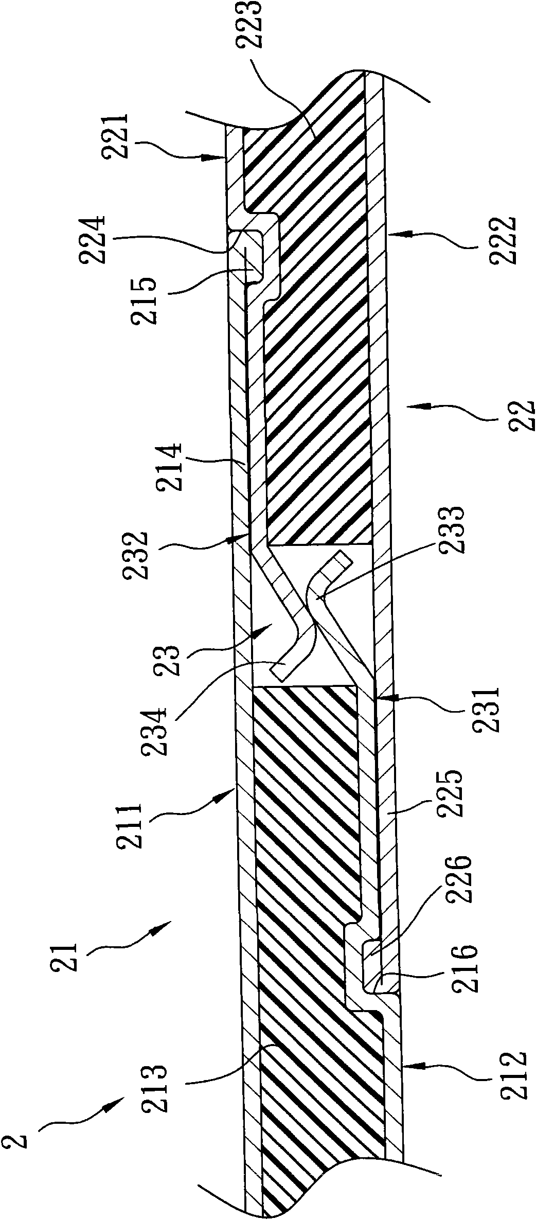
[0015] Such as figure 2 and image 3 As shown, a first preferred embodiment of the composite board assembly 2 of the present invention includes a first composite board 21, a composite board combined with the first composite board 21 through means of gluing and fastening. The second composite board 22 and a buckle unit 23 .

[0016] The first composite sheet 21 has an upper metal layer 211 , a lower metal layer 212 spaced apart from the upper metal layer 211 , and a non-metallic core layer 213 sandwiched between the upper and lower metal layers 211 , 212 . The upper metal layer 211 has a right side protruding from the non-metallic core layer 213 (corresponding to figure 2 direction, hereinafter the same), and an overlapping layer portion 214 extending from a right end of the overlapping layer portion 214 toward a direction away from the non-metallic core lay...


PUM


Abstract

The invention provides a composite plate assembly, which comprises a first composite plate, a second composite plate capable of being pressed to adhere to and integrally buckled with the first composite plate, and a buckling unit. The buckling unit comprises a buckling arm which is in integral butt joint with an end side of a lower metal layer of the first composite plate and a matching componentwhich is integrally arranged on the second composite plate and capable of being buckled with an end part of the buckling part. A structure design that the first and second composite plates are tightlybuckled by embedment, overlapping, gluing as well as the buckling unit solves the problems of time and spaced occupation for standing to wait for solidification and the like and allows the whole assembly to effectively save construction operation time, high splicing efficiency and quality and the like.

Description

【Technical field】 [0001] The invention relates to a composite board assembly, in particular to a composite board assembly assembled by means of bonding and fastening. 【Background technique】 [0002] Such as figure 1 As shown, an existing composite board 1 comprises a non-metallic core layer 11, a first metal layer 12 attached to a surface of the non-metallic core layer 11, and a first metal layer 12 attached to the non-metallic core layer 11. The stepped second metal layer 13 on the opposite surface. The first metal layer 12 has an overlapping portion 121 relatively protruding from one side of the non-metallic core layer 11 . [0003] When the two composite panels 1 are combined into one, glue is first coated on the inner surface of the overlapping portion 121 of the first metal layer 12 of each composite panel 1, and then the overlapping portion 121 of each composite panel 1 is lapped, Adhesive on the surface of the second metal layer 13 of another composite board 1, and...

Claims


Application Information

Patent Timeline
IPC IPC(8): F16S1/02F16B5/00
Inventor 郑宪得郑宪松
Owner XXENTRIA TECH MATERIALS CO LTD
Why Eureka
Try Eureka