
3D detection method for rail surface defects

A technology for three-dimensional inspection and rail, which is applied in the direction of optical testing for flaws/defects, etc. It can solve problems such as difficult grayscale image distinction, difficult lighting and image acquisition, and easy occlusion

Inactive Publication Date: 2010-02-03
UNIV OF SCI & TECH BEIJING
View PDF0 Cites 34 Cited by
  • Summary
  • Abstract
  • Description
  • Claims
  • Application Information

AI Technical Summary

Problems solved by technology

[0005] (1) The surface of the rail is not a plane but an irregular curved surface, especially the two sides. If two-dimensional detection is used for detection, the illumination and image acquisition of the two sides are very difficult and easily blocked
[0006] (2) There is a large amount of iron oxide scale on the surface of the rail, and the color of the iron oxide scale is very similar to the surface defects of the heavy rail, such as scars, indentations, etc., and it is difficult to distinguish them by grayscale images
[0007] Therefore, the traditional two-dimensional detection method cannot be directly applied to the detection of rail surface defects, and new technologies need to be developed

Method used


Image

  • 3D detection method for rail surface defects
  • 3D detection method for rail surface defects
  • 3D detection method for rail surface defects

Examples


Embodiment Construction

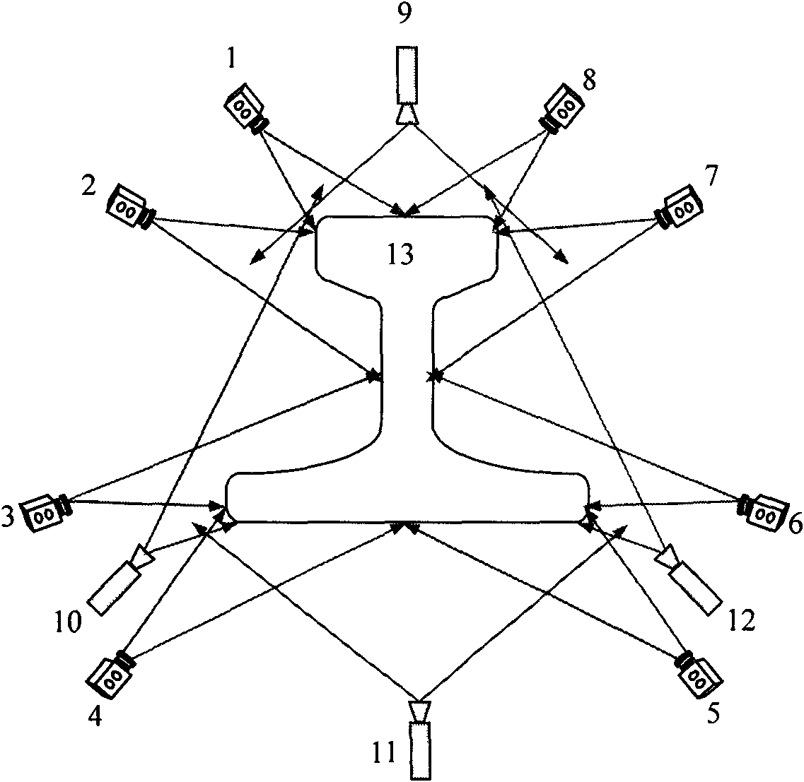
[0015] In order to realize the detection of the entire section of the rail, 8 area array CCD cameras and 4 laser line light sources are used. figure 1 Among them, the laser line light source 9 is placed directly above the top surface of the rail 13, and the emitted laser lines cover the entire top surface and two corners of the top surface; the laser line light source 11 is placed directly below the bottom surface of the rail 13, and the emitted laser lines Cover the entire bottom surface and the two corners of the bottom surface; the laser line light sources 10 and 12 are respectively placed under the two outer sides of the bottom surface of the rail 13, and the emitted laser lines cover the two sides of the rail 13 respectively, the laser line light source 9, the laser line light source 10. The laser lines emitted by the laser line light source 11 and the laser line light source 12 are on the same light plane, perpendicular to the running direction of the rail 13, and the las...


PUM


Abstract

The invention relates to a 3D detection method for rail surface defects, which can realize 3D defect online detection on four surfaces of a rail. The method comprises the following steps: laser line light sources are respectively arranged on the top surface, the bottom surface and the two sides of the rail, and the laser lines emitted by the four laser line light sources form a closed curve; meanwhile, 8 area-array CCD cameras are arranged around the rail so as to synchronously acquire a closed area formed by the laser lines; and transferring the laser line image acquired by the camera to a computer, and judging the change condition of a laser line coordinate by extracting the laser lines to detect the 3D defects on the rail surface. In the invention, the method helps transform depth variable quantity of the rail surface into a 2D gray scale image, and detect the 3D defects on the rail surface by a distribution map of surface depth variation so as to detect a defect area by an image processing algorithm, thus realizing the real-time processing capability on complex 3D data.

Description

technical field [0001] The invention belongs to the field of automatic detection, and in particular provides a three-dimensional detection method for rail surface defects and a detection device for implementing the method. Background technique [0002] Rail surface defects are an important factor affecting the safe operation of trains, especially for high-speed heavy rails. If there are surface defects, it will cause safety hazards to high-speed trains, and even cause major safety accidents. Therefore, it is necessary to strictly inspect the surface of the rail during the rail production process. With the increase of the speed and output of the rail production line, the problem of surface defect detection of the rail has become increasingly prominent, and has become an important factor limiting the output. [0003] At present, the detection of rail surface defects is mainly realized by visual inspection, that is, manually observing the rail surface with the naked eye, so as...

Claims


Application Information

Patent Timeline
IPC IPC(8): G01N21/88
Inventor 徐科徐金梧杨朝霖周鹏
Owner UNIV OF SCI & TECH BEIJING
Learn More