Firefighting guide illumination line

A lighting line and fire-fighting technology, applied to lighting devices, light sources, electrical components, etc., can solve problems such as high power consumption, inability to be operated independently by a single person, and easy heating during work

Inactive Publication Date: 2010-02-03
SHANGHAI KEYAN PHOSPHOR TECH
View PDF0 Cites 8 Cited by
  • Summary
  • Abstract
  • Description
  • Claims
  • Application Information

AI Technical Summary

Problems solved by technology

The shortcomings of the existing technology are: the point light source does not emit light continuously, and the direction cannot be recognized at a short distance indoors; the power consumption is large, 2-7 watts per meter, and a large supporting battery is required as a power supply; the diameter of the light-emitting line is thick, usually 8mm, The weight is heavy, the continuous length is short, the work is easy to generate heat, and it is easy to break at a small angle; the existing external plastic pipe is mainly PVC plastic, which is colored with fluorescent pigments, and the luminous transparency is low. Fluorescent dyes with good transparency are easy to decolorize in PVC and cannot be used.
In addition, when the wire wheel rotates, the light-emitting work is easy to short circuit, which makes it impossible for a single person to operate independently
Due to the existence of the above-mentioned problems, such technologies and products cannot be popularized and used on a large scale
[0004] Long afterglow luminous guide rope is also a commonly used technology. Its disadvantage is that it needs a strong light source to continuously illuminate the entire surface of the rope for 3-5 minutes, which is difficult to complete in emergency use, and the effective light is only less than 30 minutes.

Method used


Image

  • Firefighting guide illumination line
  • Firefighting guide illumination line

Examples


Embodiment

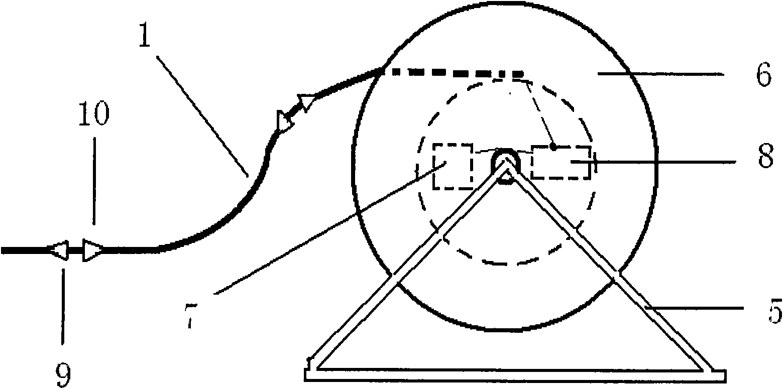
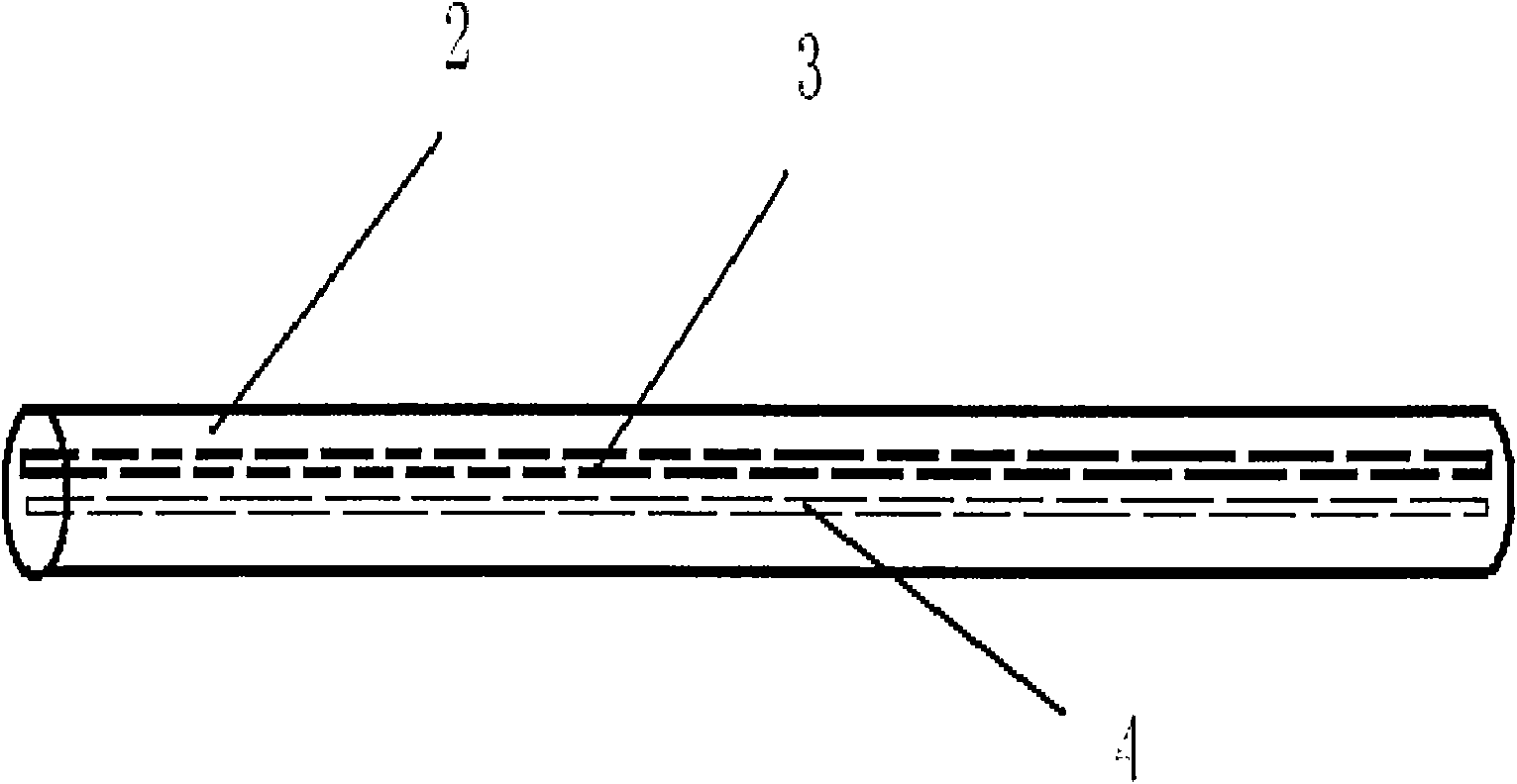
[0028] A powerful electroluminescent wire (1) with a length of 100 meters that continuously emits light. The outside of the powerful electroluminescent wire is a PVC colorless transparent plastic layer (2), and the inside of the powerful electroluminescent wire is an electroluminescent wire that emits blue-green light The core (3) and the flexible long afterglow luminous steel wire rope (4) parallel to it; the strong electroluminescent wire is made by using a wire extruder. The powerful electroluminescent wire is wound on a rotatable iron wire reel (6) with an iron bracket (5). The rechargeable battery (7) and drive controller (8) are arranged in the center of the wire reel, and are connected with the electroluminescent wire One end of the core is connected in series, the light-emitting line can emit light continuously when the power is turned on, and the light-emitting line can be retracted and released at will by using the wire reel wheel.

[0029] The surface of the PVC tra...


PUM


Abstract

The invention relates to a firefighting guide illumination line comprising a continuously luminous strong electroluminescence line (1), a PVC transparent plastic layer (2), an electroluminescence line(3) and a flexible wire cable (4) parallel to the electroluminescence line (3), wherein the PVC transparent plastic layer (2) is arranged outside the strong electroluminescence line (1); the electroluminescence line (3) and the flexible wire cable (4) are arranged in the strong electroluminescence line (1) which is wound on a rotatable wire coil wheel (6) with a stand (5); the center of the wirecoil wheel (6) is provided with charging batteries (7) and a driving controller (8) and is connected in series with one end of the strong electroluminescence line (1); the power-on strong electroluminescence line (1) can continuously illuminate when being electrified, and the wire coil wheel (6) is used to randomly withdraw and release the strong electroluminescence line (1). The firefighting guide illumination line is mainly applied to underground places, such as markets, subways, coal mine, and the like for rescue and guides refugees to evacuate towards a destination direction.

Description

technical field [0001] The invention belongs to the technical field of fire safety lighting. Background technique [0002] The fire guiding lighting line is mainly used in the rescue of shopping malls, subways, coal mines and other underground places, and guides the trapped people to evacuate according to the planned target direction. [0003] The prior art uses LED or neon bulb lighting sources, which are point light sources arranged in series, so they are also called string lights, and their original purpose is mainly used for outdoor decorative lighting during festivals. The shortcomings of the existing technology are: the point light source does not emit light continuously, and the direction cannot be recognized at a short distance indoors; the power consumption is large, 2-7 watts per meter, and a large supporting battery is required as a power supply; the diameter of the light-emitting line is thick, usually 8mm, The weight is heavy, the continuous length is short, th...

Claims


Application Information

Patent Timeline
Patent Type & Authority Applications(China)
IPC IPC(8): H05B33/00
Inventor 郑岩边静宇耿树范史陈峰张永亮费运启刘承辉全丽华蒋赟沈君萍王翠萍
Owner SHANGHAI KEYAN PHOSPHOR TECH
Why Eureka
Try Eureka