Electronic ballast applying piezoelectric ceramic transformer

A technology of electronic ballasts and piezoelectric ceramics, applied in piezoelectric/electrostrictive/magnetostrictive devices, circuits, electric light sources, etc., can solve the problems of product parasitic parameter deviation, damage, and loss of stability of resonant circuits, etc. To achieve the effect of broadening the frequency range

Inactive Publication Date: 2010-02-03
MORNSUN GUANGZHOU SCI & TECH
View PDF0 Cites 3 Cited by
  • Summary
  • Abstract
  • Description
  • Claims
  • Application Information

AI Technical Summary

Problems solved by technology

After preheating and lighting, the impedance changes greatly. It is difficult to ensure that the circuit works in an inductive state when the load impedance of the fluorescent lamp changes by using a traditional circuit. Once the circuit works in a capacitive state, the resonant circuit will lose stability or even be damaged. destroy
[0006] 2. Even if the appropriate circuit parameters can be found so tha

Method used


Image

  • Electronic ballast applying piezoelectric ceramic transformer
  • Electronic ballast applying piezoelectric ceramic transformer
  • Electronic ballast applying piezoelectric ceramic transformer

Examples


Example Embodiment

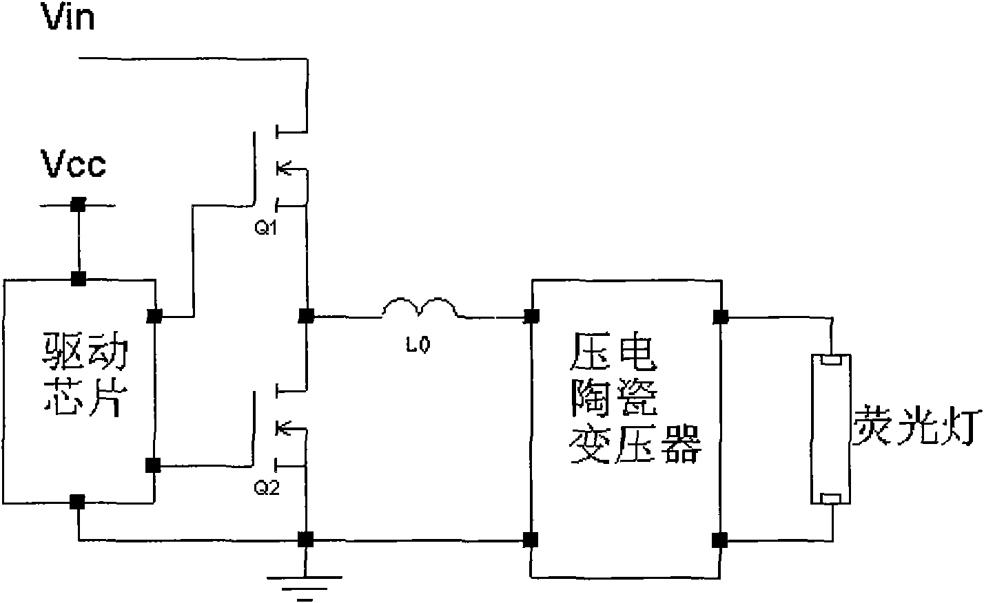
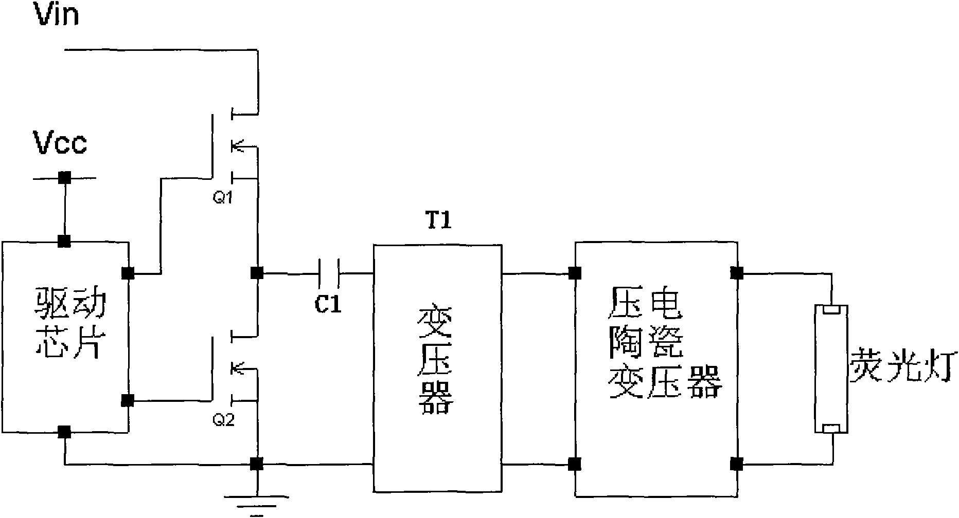
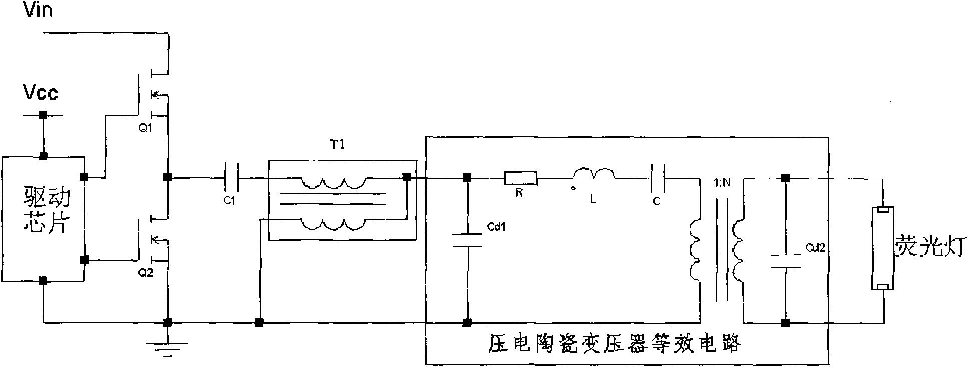
[0021] Such as image 3 As shown in the first embodiment, the present invention proposes to increase the transformer T1 on the basis of the original circuit. The function of the transformer T1 is to change the amplitude and phase of the subsequent stage voltage to adjust the working voltage point of the piezoelectric ceramic transformer. Through the appropriate turns ratio of the two windings of the transformer T1 and the coupling degree of the windings, the entire circuit works in an inductive state .

[0022] The driving chip, MOS transistors Q1 and Q2 are connected to form a square wave pulse voltage generating circuit, which can also use other square wave pulse voltage generating circuits in the prior art; the driving chip drives the MOS transistors Q1 and Q2 to turn on in turn, and the input voltage Vin is MOS transistors Q1 and Q2 output stable square wave pulse voltages. One end of the primary winding of the regulator transformer T1 is connected to the output of the square...


PUM


Abstract

The invention provides an electronic ballast applying a piezoelectric ceramic transformer, comprising a square wave pulsed voltage generating circuit, the piezoelectric ceramic transformer and a regulating transformer, wherein, the regulating transformer is connected between the output end of the square wave pulsed voltage generating circuit and the input end of the piezoelectric ceramic transformer, back-stage voltage amplitude and phase can be changed by adjusting the transformer, and the working pressure point of the piezoelectric ceramic transformer is adjusted to ensure that the whole circuit works under the inductive state. The invention can greatly enlarge the frequency range of the piezoelectric ceramic transformer when the piezoelectric ceramic transformer works under the inductive state, thus ensuring that the whole circuit still works under the inductive state in the condition of fluorescent lamp load impedance change so as to prevent the resonance circuit from losing stability.

Description

Technical field [0001] The invention relates to an electronic ballast, in particular to a high-reliability electronic ballast using a piezoelectric ceramic transformer. Background technique [0002] With the gradual maturity of the piezoelectric ceramic transformer technology and the gradual decrease in cost, the piezoelectric ceramic transformer will be more widely used in many suitable fields. Piezoelectric ceramic transformers have many advantages that traditional transformers do not have. In the field of electronic ballasts for fluorescent lamps, it is undoubtedly very suitable for piezoelectric ceramic transformer applications. Therefore, a comprehensive and in-depth study of the application of piezoelectric ceramic transformers in the field of electronic ballasts is very necessary. [0003] The piezoelectric ceramic transformer is applied to the traditional LC resonant circuit as attached figure 1 Shown. It mainly includes the driver chip, MOS transistors Q1, Q2, inductor ...

Claims


Application Information

Patent Timeline
IPC IPC(8): H05B41/24H01L41/107
Inventor 龚晟黄江剑张红军
Owner MORNSUN GUANGZHOU SCI & TECH
Why Eureka
Try Eureka