Radiating device

A technology of heat dissipation device and heat dissipation fins, which is applied to heat exchange equipment, indirect heat exchangers, lighting and heating equipment, etc. Stable performance and easy assembly

Inactive Publication Date: 2010-02-03
FU ZHUN PRECISION IND SHENZHEN +1
View PDF0 Cites 5 Cited by
  • Summary
  • Abstract
  • Description
  • Claims
  • Application Information

AI Technical Summary

Problems solved by technology

However, the opening will reduce the area of ​​the heat dissipation fins, and the operation of the heat dissipation device is cumbersome to assemble

Method used


Image

  • Radiating device
  • Radiating device
  • Radiating device

Examples


no. 1 example

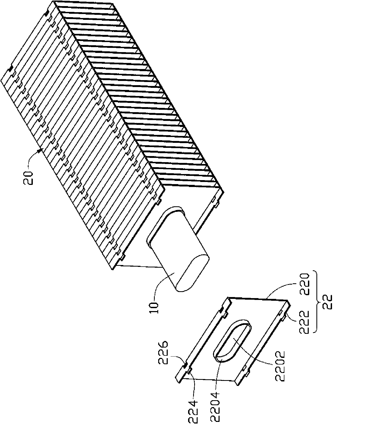
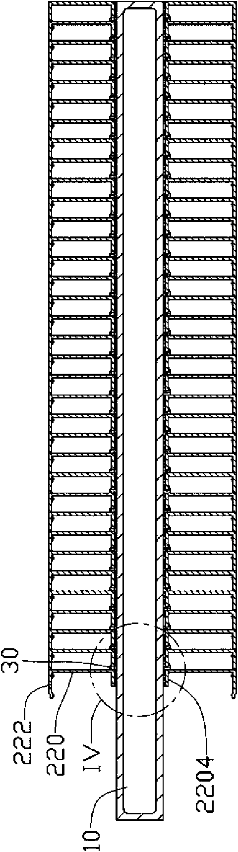
[0015] like figure 1 and figure 2 Shown is the first embodiment of the heat dissipation device of the present invention. The heat dissipation device includes a heat dissipation fin set 20 and a heat pipe 10 passing through the heat dissipation fin set 20 .

[0016] The heat pipe 10 is a flat heat pipe.

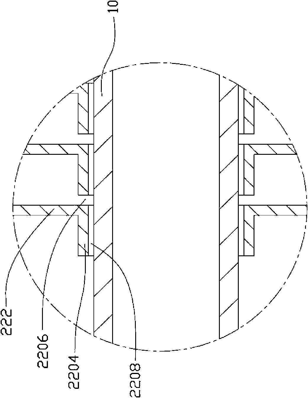
[0017] The heat dissipation fin set 20 is formed by a plurality of heat dissipation fins 22 arranged in sequence. The heat dissipation fins 22 are parallel to each other, and every two adjacent heat dissipation fins 22 are spaced an equal distance from each other to form an airflow channel. Each cooling fin 22 includes a body 220 and two folded edges 222 respectively bent from the top and bottom of the body 220 to one side. The folded edges 222 are perpendicular to the body 220. Each folded edge 222 includes a fixed end connected to the main body 220 and a free end extending outward from the fixed end. The widths of the two folded edges 222 are equal. The side 222 has a c...


PUM


Abstract

The invention relates to a radiating device, comprising a heat pipe and a plurality of radiating fins, wherein each radiating fin comprises a main body and an edgefold formed by bending to one side from the end of the main body, and the edgefold abuts against the main body of the adjacent radiating fin; the main body of each radiating fin is provided with a through hole, and each main body extendsalong the circumference of the through hole to the direction of the main body of the adjacent radiating fin to form a ring edge; the ring edges form an accommodating channel which accommodates the heat pipe; the ring edge at least has a part whose height is smaller than the width of the edgefold so that a gap is formed between the part of the ring edge and the main body of the adjacent radiatingfin, and the gap is used for accommodating excessive solder paste filled between the heat pipe and the radiating fin; thus, when the heat pipe penetrates through the accommodating piece formed by thethrough holes, excessive solder paste can not be extruded out and can remain inside the gap, thus the solder paste can be effectively used.

Description

technical field [0001] The invention relates to a heat dissipation device, in particular to a heat dissipation device for heat dissipation of electronic components. Background technique [0002] Electronic components (such as central processing unit) generate a lot of heat during operation, which increases the temperature of itself and the system, which in turn leads to a decrease in its operating performance. In order to ensure the normal operation of the electronic components, a cooling device is usually installed on the electronic components to dissipate the heat generated by them. [0003] The existing heat dissipation device generally includes a heat pipe and a plurality of heat dissipation fins. Each cooling fin is provided with a perforation, and a ring edge protrudes outward along the periphery of the perforation. During assembly, the ring edge of each cooling fin abuts against the adjacent cooling fins to form a closed storage channel, the inner surface of the sto...

Claims


Application Information

Patent Timeline
Patent Type & Authority Applications(China)
IPC IPC(8): H05K7/20H01L23/367H01L23/427
CPCF28D15/0275F28F1/24F28D15/02
Inventor 陈荣安
Owner FU ZHUN PRECISION IND SHENZHEN
Why Eureka
Try Eureka