Controller and control system for a pressure reducing valve

A technology of controllers and pressure reducing valves, which is applied in electric fluid pressure control, water supply pipeline systems, buildings, etc., and can solve problems such as critical point changes

Active Publication Date: 2010-02-03
MUELLER INT LLC
View PDF2 Cites 18 Cited by
  • Summary
  • Abstract
  • Description
  • Claims
  • Application Information

AI Technical Summary

Problems solved by technology

However, it is understood that there may be more than one critical point in a particular DMA, and that the critical point may vary
[0005] A problem with this design is that at a certain time or under certain conditions in the DMA, the fixed pressure may be higher than necessary to ensure proper pressure at the or each critical point

Method used


Image

  • Controller and control system for a pressure reducing valve
  • Controller and control system for a pressure reducing valve
  • Controller and control system for a pressure reducing valve

Examples


Embodiment Construction

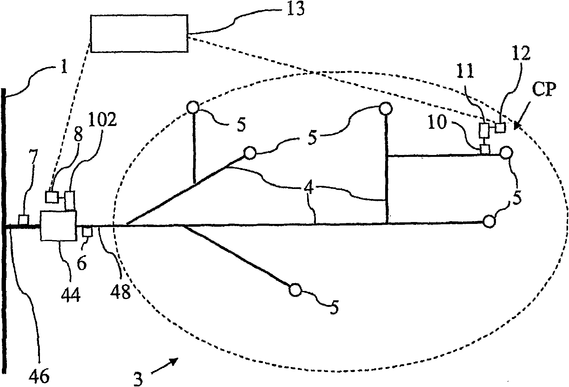
[0129] Referring to the accompanying drawings below, figure 1 Shown is an aortic water supply pipeline 1, the aortic water supply pipeline 1 supplies water with a water pressure of P1 to a pressure reducing valve (PRV) 44 through a pipeline 46, and then supplies reduced water to a measurement area (DMA) 3 through an output pipeline 48. The output water pressure is P2 water, and the DMA area includes a large number of pipelines 4 supplying water to a large number of users 5 . One of the users 5 is set to the critical point CP where the pressure P3 is significantly lower than elsewhere in the DMA 3 area due to the distance from the critical point CP to the PRV 44 and / or the height of the critical point with respect to the PRV . Although only one critical point is indicated in this embodiment, other embodiments may have multiple critical points.

[0130] Adjacent to the PRV 44 are provided a first pressure measurement sensor 6 for measuring the output pressure P2 of the PRV, and ...


PUM


Abstract

A controller (8) for a pilot valve (102) which adjusts the output pressure of a pressure reducing valve (44) supplying water to a consumer region (3). With the aim of reducing output pressure whilst still providing a minimum required pressure at a critical point (CP) in the region, the controller adjusts the output pressure in accordance with the flow rate. The controller includes a clock (22) andthe relationship between the required output pressure and the measured flow rate is time dependent. Parameters which define the relationship are supplied to the controller (8) from a remote data processing system (13) which analyses flow rate and output pressure data transmitted from the controller, and also pressure data from a remote sensor (10) at'the critical point. At intervals, the controller (8) establishes a wireless connection with the remote system (13), to transmit logged data, and to receive parameters covering a period of time which is greater than the interval between communication sessions.

Description

technical field [0001] The present invention relates to a controller and control system for regulating the output pressure of a pressure reducing valve supplying water to a water consumption area. The present invention relates in part, but not exclusively, to the control of a pilot valve for varying pressure relief valve pressure. Background technique [0002] In a preferred embodiment, the present invention relates to the control of water pressure supplied from a high pressure main supply to water areas, and in particular to the supply of water to individual metered divisions (DMAs). However, the invention can also be used in other circulation systems, eg in large industrial centers. [0003] The pressure of the main water distribution system is generated by the gravity pressure difference of the pumps and / or the water in the reservoir, water tower or similar structure. The water pressure in the aortic supply line is much greater than the water pressure for domestic, agri...

Claims


Application Information

Patent Timeline
Patent Type & Authority Applications(China)
IPC IPC(8): G05D16/20E03B7/07
Inventor 安德鲁·罗兰·伯罗斯
Owner MUELLER INT LLC
Why Eureka
Try Eureka