
Security punching machine capable of realizing jogging control of punching head

A kind of jog control and safety technology, applied in the field of stamping machinery, can solve the problems of physical injury, reduce work efficiency, inconvenient operation, etc., and achieve the effect of high safety, convenient operation and high control precision.

Inactive Publication Date: 2010-02-10
天津市瑞亨机械开发有限公司
View PDF7 Cites 8 Cited by
  • Summary
  • Abstract
  • Description
  • Claims
  • Application Information

AI Technical Summary

Problems solved by technology

In this way, it not only causes inconvenience in operation and reduces work efficiency, but also easily causes the operator to extend his hand under the punch due to negligence during the operation process, resulting in accidents such as personal injury.

Method used


Image

  • Security punching machine capable of realizing jogging control of punching head
  • Security punching machine capable of realizing jogging control of punching head
  • Security punching machine capable of realizing jogging control of punching head

Examples


Embodiment Construction

[0019] The embodiments of the present invention will be described in further detail below in conjunction with the accompanying drawings. The following embodiments are only descriptive, not restrictive, and cannot limit the protection scope of the present invention.

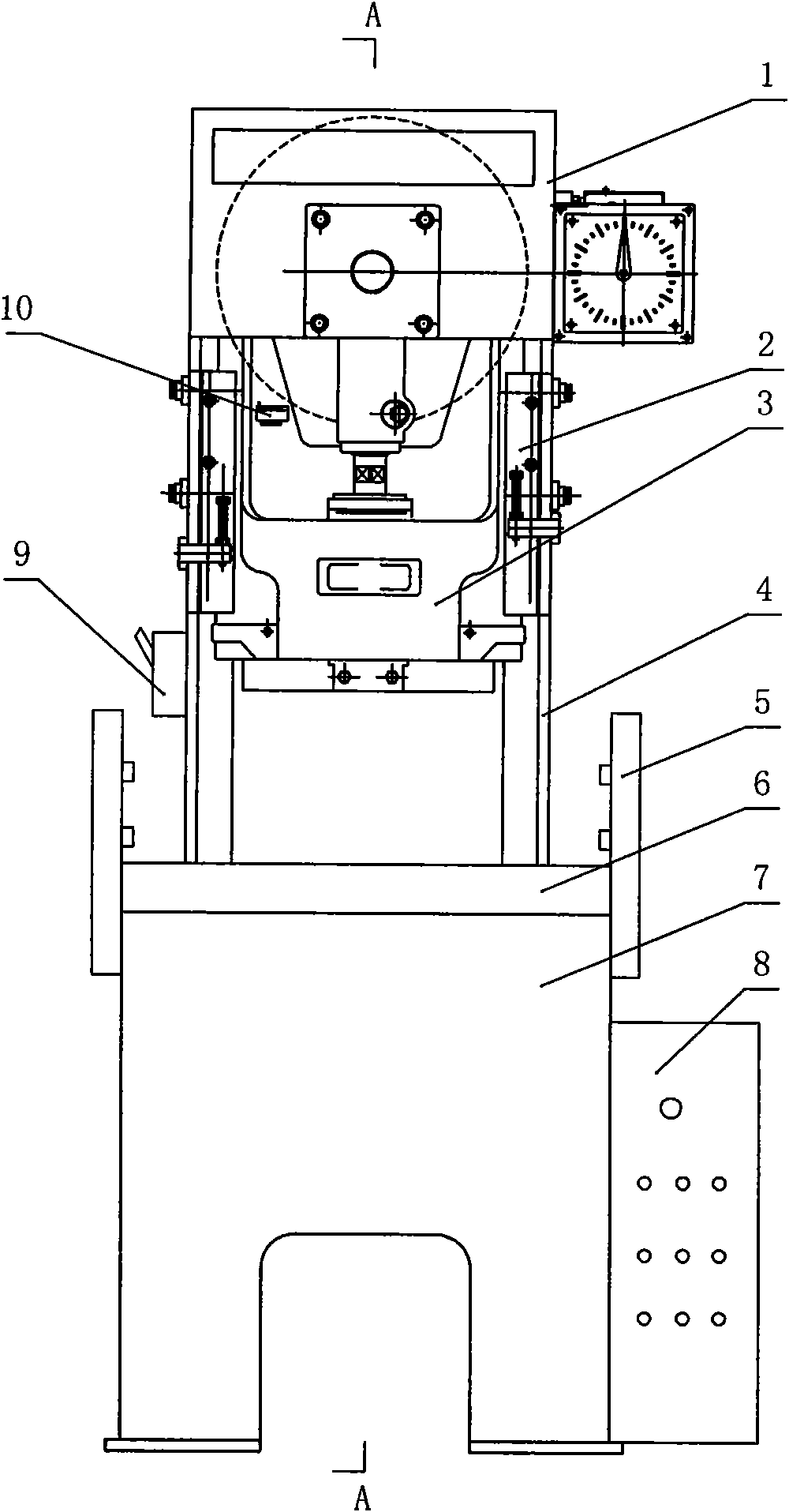
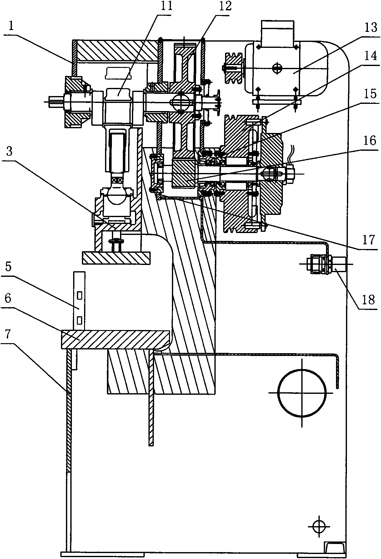
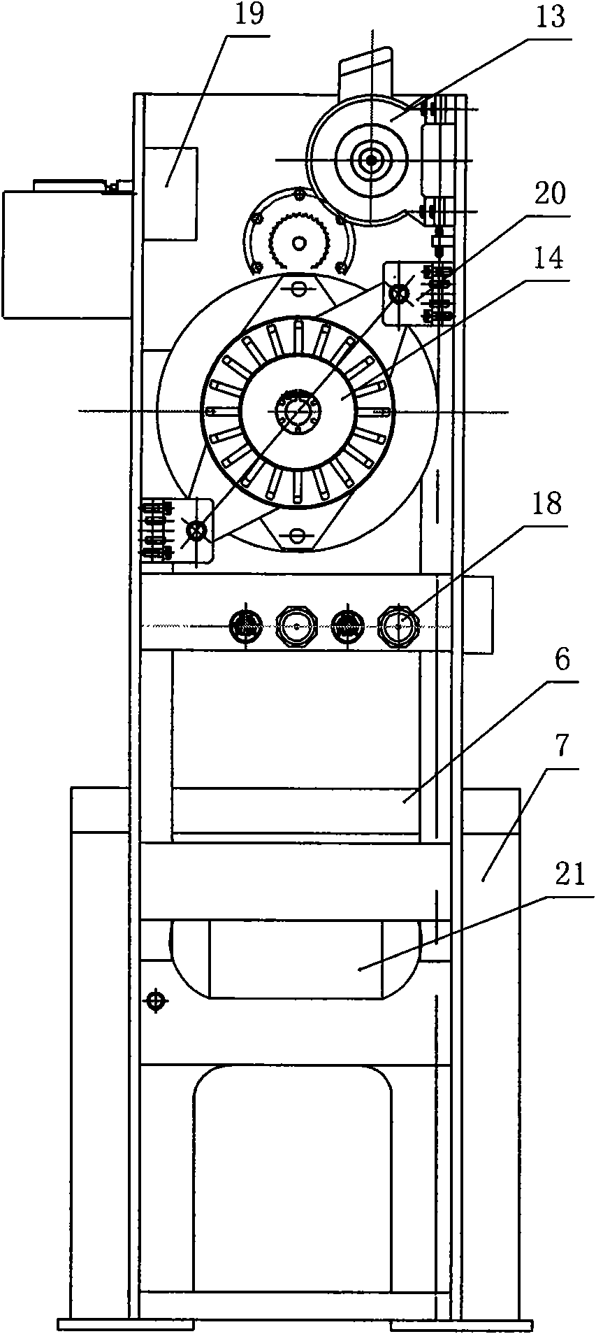
[0020] A safety punching machine capable of realizing punch inching control, consisting of a workbench 6, a frame 4, a punch 3, a crankshaft 11, and a drive motor 13, the workbench is fixed on the upper surface of a base 7, and the upper surface of the base is fixed Install the rack. The vertical lifting movement of the punch is installed on the side plate of the frame at the top of the workbench, and the sliding block both sides of the punch are guided and installed on the frame side plate by the bead 2. Rotate and install a crankshaft on the top plate 1 on the upper part of the frame, the connecting sleeve on the upper part of the punch is fitted on the front end of the crankshaft, and the rear end of the cranks...


PUM


Abstract

The invention relates to a security punching machine capable of realizing jogging control of a punching head, which consists of a worktable, a stander, the punching head, a crank shaft and a driving motor, wherein the punching head is longitudinally and movably arranged on the stander on the upper part of the worktable and is sleeved at the front end of the crank shaft, and the back end of the crank shaft and the driving motor which is fixedly arranged on the back surface of the stander are arranged in linkage. The security punching machine has the following innovative points that: the other end of the crank shaft is provided with an output end big gear wheel of a reducing gear set in a driven mode; a driving shaft of an input end small gear wheel of the reducing gear set is fixedly provided with a driven disk of a pneumatic clutch; and a driving disk of the pneumatic clutch is in linkage with an output shaft of the driving motor. The security punching machine has a scientific and reasonable structural design, realizes the jogging control of the punching head by controlling the engagement and the disengagement of the pneumatic clutch, facilitates die alignment, and has the advantages of stable running, precise control, convenient operation, safe use and the like.

Description

technical field [0001] The invention belongs to the field of stamping machinery, in particular to a safety punch capable of realizing punch inching control. Background technique [0002] Punch is a very common mechanical processing device. At present, the punches of most mechanical punches are driven by rotating the crankshaft to realize the rise and fall of the punch from the highest point to the lowest point of its stroke. However, the existing crankshaft rotates continuously during the rotation process, that is, the punch cannot stop during the operation between the highest point and the lowest point of the stroke, and when placing the lower mold, it is only aligned by the experience of the operator. , with poor alignment accuracy. Since the punch cannot stop during the action, once the punch starts to move, the position of the mold can no longer be adjusted, and the punch must be stopped by means of stopping. Like this, not only causes the inconvenience of operation, r...

Claims


Application Information

Patent Timeline
Patent Type & Authority Applications(China)
IPC IPC(8): B30B15/12
Inventor 刘景瑞
Owner 天津市瑞亨机械开发有限公司
Learn More