Method for controlling combustion noise in a compression-ignition engine

A combustion engine, combustion noise technology, applied in the direction of combustion engine, internal combustion piston engine, engine control, etc., can solve problems such as high pressure, increased noise level, and increased speed

Inactive Publication Date: 2010-02-10
GM GLOBAL TECH OPERATIONS LLC
View PDF12 Cites 11 Cited by
  • Summary
  • Abstract
  • Description
  • Claims
  • Application Information

AI Technical Summary

Problems solved by technology

Engines with advanced combustion timing will have a highe...

Method used


Image

  • Method for controlling combustion noise in a compression-ignition engine
  • Method for controlling combustion noise in a compression-ignition engine
  • Method for controlling combustion noise in a compression-ignition engine

Examples


Embodiment Construction

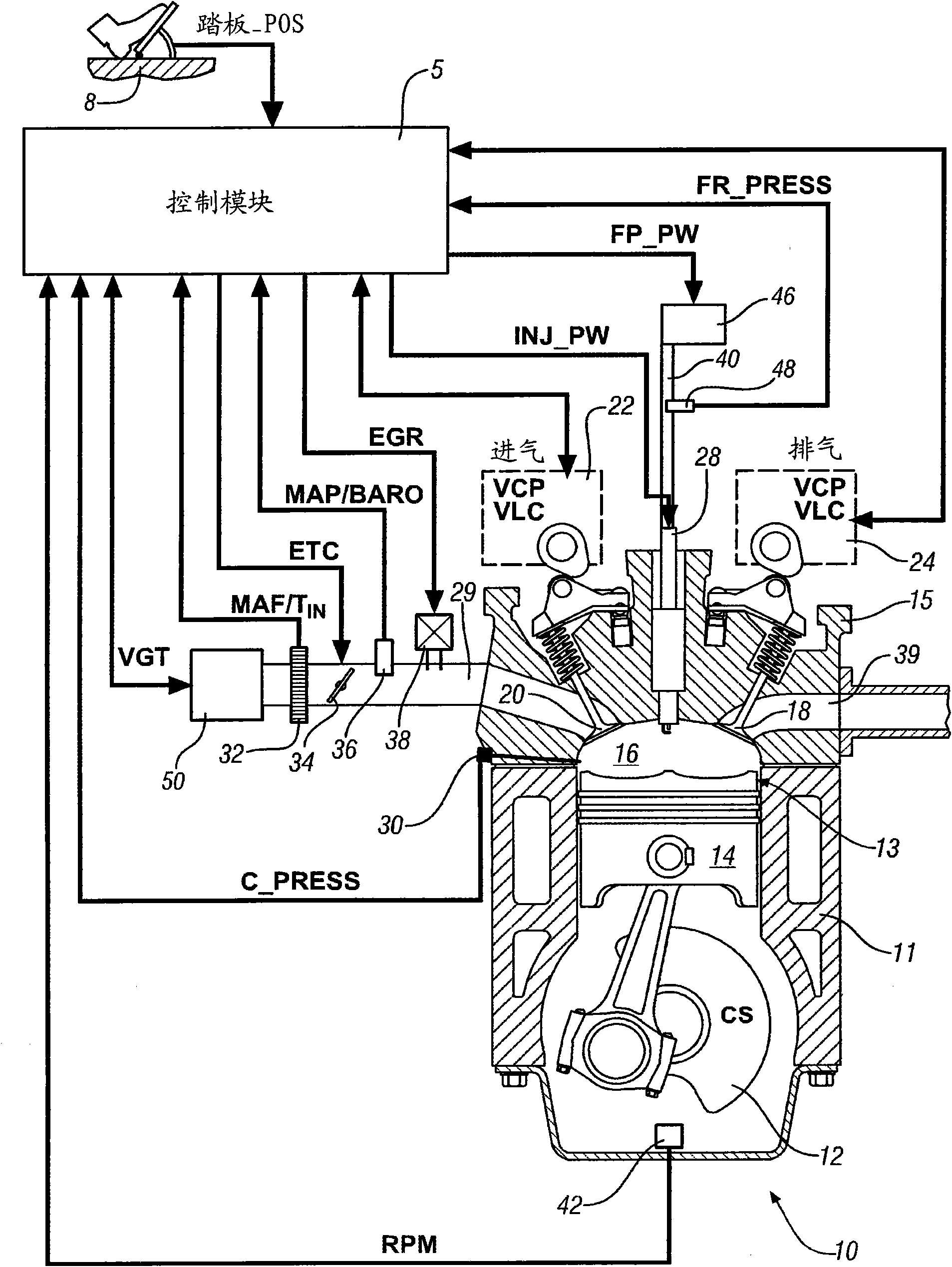
[0011] [0011] Referring now to the drawings, in which the illustrations are for the purpose of illustrating certain exemplary embodiments only and are not intended to be limiting, figure 1 A compression ignition internal combustion engine 10 and a control module 5 are schematically shown. Exemplary internal combustion engine 10 includes a multi-cylinder arrangement including an engine block 11 , a crankshaft (“CS”) 12 and cylinder heads 15 . In the engine block 11 are formed a plurality of cylinders 13 each having a piston 14 slidably movable therein. Each piston 14 is mechanically operatively connected via a piston rod to the crankshaft 12, and the crankshaft 12 is mounted to the engine block 14 on main bearings and rotates therein. The linear reciprocating motion of piston 14 is converted into rotational motion of crankshaft 12 . The intake system directs the intake air to the intake manifold 29 which directs and distributes the intake air to a plurality of intake runners....


PUM


Abstract

Combustion noise in a compression-ignition engine is controlled by measuring in-cylinder pressure of a cylinder of the compression-ignition engine, determining a combustion noise level based on the in-cylinder pressure measurement, and modifying a combustion control parameter based on the combustion noise level.

Description

technical field [0001] [0001] The present invention relates to a compression ignition engine control system. Background technique [0002] [0002] The statements in this section merely provide background information related to the present disclosure and may not constitute prior art. [0003] [0003] Compression ignition engines, such as diesel engines, operate by injecting fuel directly into the combustion chamber. Manufacturers of compression ignition engines have developed various combustion modes to reduce engine emissions. Exemplary combustion modes include premixed charge compression combustion ("PCCI") and homogeneous charge compression combustion ("HCCI"). These combustion modes may employ advanced injection timing in conjunction with high exhaust gas recirculation rates to create a premixed or more homogeneous combustion mixture upon combustion. Compression ignition engines employing advanced combustion modes may exhibit increased pressure levels and increased press...

Claims


Application Information

Patent Timeline
IPC IPC(8): F02D41/14F02D41/40F02D43/00
CPCF02D41/401Y02T10/44F02D35/023F02D41/3836Y02T10/40
Inventor I·哈斯卡拉Y·-Y·王C·-B·M·关F·A·马特库纳斯P·A·贝蒂森
Owner GM GLOBAL TECH OPERATIONS LLC
Why Eureka
Try Eureka