
Exhaust Gas Purifying Method and Purifier

a technology of exhaust gas and purification method, which is applied in the direction of engine controllers, machines/engines, electric control, etc., can solve the problems of relatively slow change, advanced or delayed fuel timing,

Active Publication Date: 2008-08-28
ISUZU MOTORS LTD
View PDF4 Cites 11 Cited by
  • Summary
  • Abstract
  • Description
  • Claims
  • Application Information

AI Technical Summary

Benefits of technology

[0015]The present invention is made to solve the above problems, and has an object to provide an exhaust gas purification method and an exhaust gas purification system capable of, in the exhaust gas purification system comprising the NOx purification catalyst for recovering the NOx purifying ability to purify NOx in the exhaust gas when the exhaust gas flowing in is in the rich condition, preventing the misfire, combustion noise, torque change, and deterioration in drivability and the like caused by excessively advanced angle or delayed angle of the injection timing of fuel injection into the cylinder during the transition to the rich condition or transition to a lean condition.
[0018]With this method, the injection timing of fuel is not advanced or delayed in angle at once to a predetermined target timing during the switching intervals between the lean and rich combustion conditions in the regeneration control for recovering the NOx purifying ability of the NOx purification catalyst. But, the injection timing of fuel is advanced or delayed in angle in response to the combustion air / fuel ratio in the cylinder, which exhibits a relatively slow change due to the air-intake throttling and EGR control in the air-intake system. This suppresses the NOx generation, combustion noise generation, rapid change in torque, deterioration in drivability, etc.
[0022]The exhaust gas purification system having the above configuration enables the above exhaust gas purification method to be performed, and the same effect as those in the method to be produced.
[0025]The exhaust gas purification system can provide and produce large effects if the NOx purification catalyst is a NOx occlusion reduction type catalyst for occluding NOx when the air / fuel ratio of the exhaust gas is in the lean condition, and releases and for reducing the occluded NOx when it is in the rich condition, or a NOx direct reduction type catalyst that reduces and purifies the NOx when the air / fuel ratio of the exhaust gas is in the lean condition, and for recovering the NOx purifying ability when it is in the rich condition.
[0027]As described above, the exhaust gas purification method and exhaust gas purification system according to the present invention advance or delay in angle the fuel injection time in response to the change of the combustion air / fuel ratio (air excess ratio λ) in the cylinder that is caused by the air-intake throttling and EGR control in the air-intake system, during the switching intervals between the combustion condition where the combustion air / fuel ratio in the cylinder becomes lean and that where it becomes rich in the regeneration control for recovering the NOx purifying ability of the NOx purification catalyst, without advancing or delaying the injection timing of the fuel at once to the predetermined timing, and thereby, can prevent the NOx generation, combustion noise, rapid change in torque, and extreme deterioration in drivability or the like.

Problems solved by technology

But, the injection timing of fuel is advanced or delayed in angle in response to the combustion air / fuel ratio in the cylinder, which exhibits a relatively slow change due to the air-intake throttling and EGR control in the air-intake system.

Method used


Image

  • Exhaust Gas Purifying Method and Purifier
  • Exhaust Gas Purifying Method and Purifier
  • Exhaust Gas Purifying Method and Purifier

Examples


Embodiment Construction

[0035]The exhaust gas purification method and exhaust gas purification system according to an embodiment of the present invention will hereinafter be described with reference to the drawings.

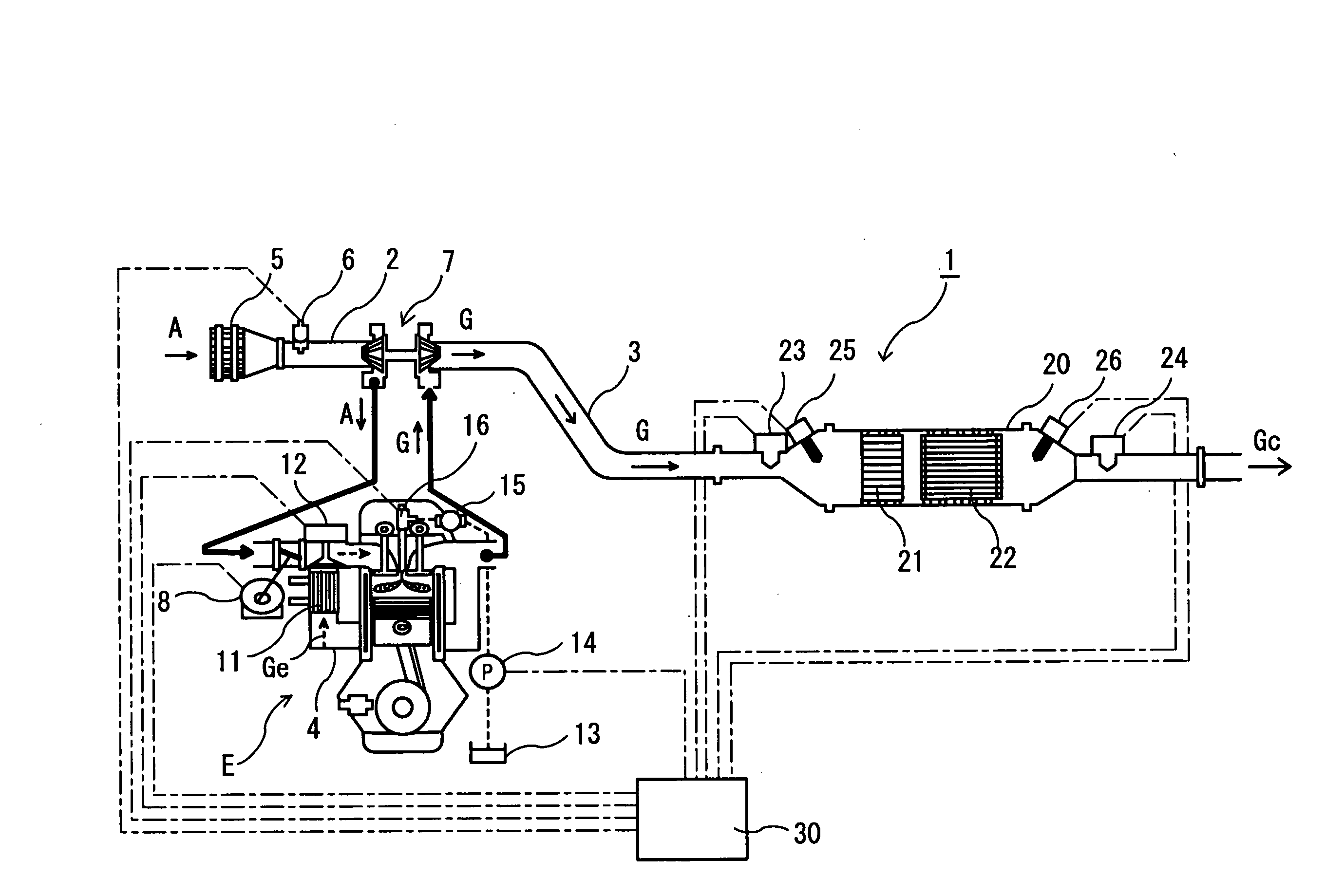
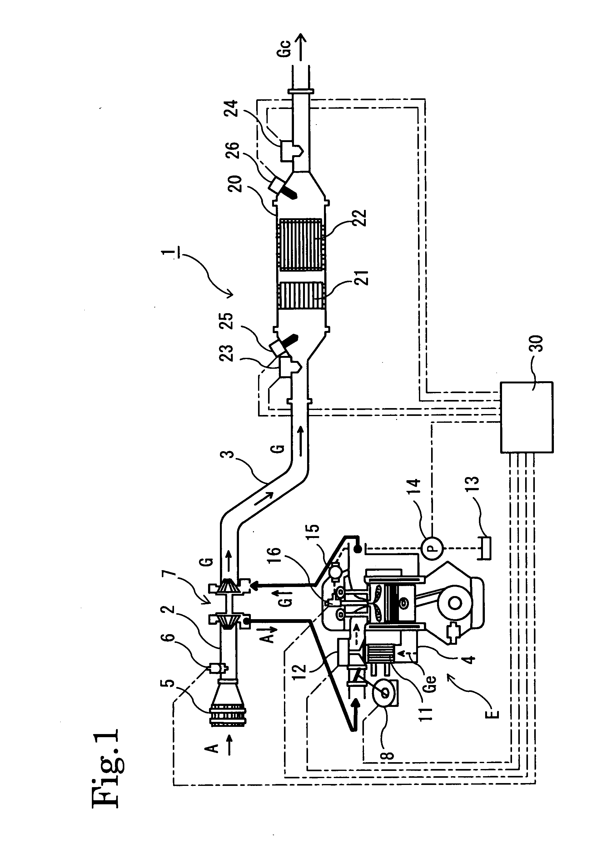
[0036]FIG. 1 shows a configuration of the exhaust gas purification system 1 according to the embodiment of the present invention. In the exhaust gas purification system 1, an exhaust gas purification device 20 comprising an oxidation catalyst 21 and a NOx occlusion reduction type catalyst 22 is arranged in an exhaust passage 3 of an engine (internal combustion engine) E.

[0037]The oxidation catalyst 21 is formed as follows: a catalyst coat layer such as activated aluminum oxide (Al2O3) is provided on a surface of a support body made of honeycomb cordierite or heat resistant steel. The catalyst coat layer is made to support a catalyst active component made of a noble metal such as platinum (Pt), palladium (Pd) and rhodium (Rh). The oxidation catalyst oxidizes HC, CO, etc. in exhaust gas flowing th...


PUM


Abstract

An exhaust gas purification system (1) performing regeneration control in a rich condition by using control of an intake system for reducing the quantity of intake air together with control of a fuel system for increasing fuel injection amount into a cylinder, wherein the timing (Tn) for injection fuel into the cylinder is varied in response to the continuous variation (λn) of air fuel ratio in the cylinder during the switching intervals (t1,t2) between lean condition and rich condition at the time of regeneration control of NOx purification catalyst (12). During a period of transition to rich condition or lean condition, misfiring, combustion noise, torque variation, deterioration in drivability, and the like, due to undue advance angle or lag angle in the timing for injecting fuel into the cylinder can thereby be prevented.

Description

FIELD OF THE INVENTION[0001]The present invention relates to an exhaust gas purification method and an exhaust gas purification system, comprised of a NOx purification catalyst that reduces and purifies NOx (nitrogen oxide) in exhaust gas from internal combustion engines.DESCRIPTION OF THE RELATED ART[0002]There have been different NOx catalysts studied and proposed for use in reducing and removing NOx in exhaust gas from internal combustion engines that includes diesel engines and some gasoline engines, and from various other combustion devices. Those NOx catalysts include a NOx occlusion reduction type catalyst and a NOx direct reduction type catalyst as the DeNOx catalyst for use in diesel engines. Using these catalysts enables NOx in the exhaust gas to be effectively purified.[0003]The NOx occlusion reduction type catalyst is a catalyst in which an oxide support layer such as alumina (Al2O3) or zeolite supports a catalytic noble metal facilitating a redox reaction, and NOx occlu...

Claims


Application Information

Patent Timeline
Patent Type & Authority Applications(United States)
IPC IPC(8): F01N3/00
CPCF01N3/0814F01N2560/02F01N13/0097F02D41/027F02D41/307F01N2560/06
Inventor FISHER, JUDITH L.VOSS, LAWRENCE J.
Owner ISUZU MOTORS LTD
Learn More