Piston, internal combustion engine and compressor of circular slider-crank mechanism of single cylinder engine
A technology of a crank round slider and a single-cylinder machine, which is applied in the directions of pistons, cylindrical pistons, machines/engines, etc., can solve the problem of unable to ensure the smooth rotation of reciprocating motion and rotary motion, and achieve a clear direction of rotation, reduce energy loss, Create simple effects
- Summary
- Abstract
- Description
- Claims
- Application Information
AI Technical Summary
Problems solved by technology
Method used
Image
Examples
Embodiment 1
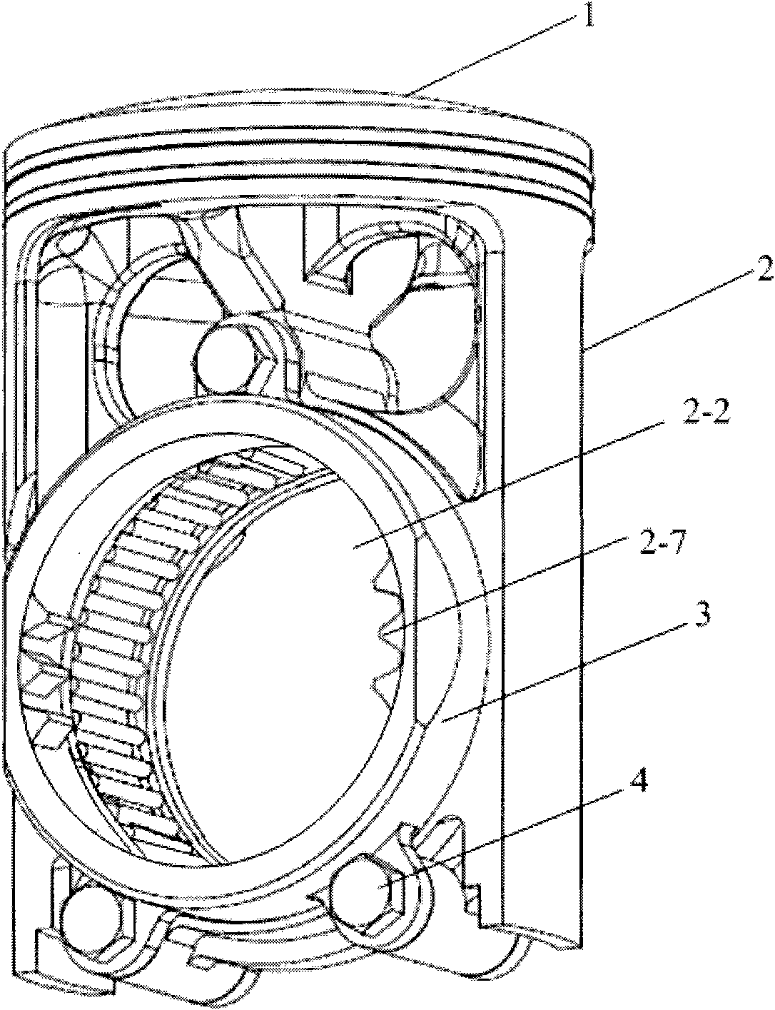
[0033] figure 1 It is a schematic diagram of the first embodiment of the piston of the crank-slider mechanism of the single-cylinder engine of the present invention.
[0034] Such as figure 1 As shown, the piston of this embodiment includes a crown 1 , a piston seat 2 and a piston stopper 3 . Wherein, the crown 1 is arranged at one end of the piston seat 2 . The crown 1 and the piston seat 2 can be integrally formed, or fixedly connected as a whole by means of riveting or screwing. In this embodiment, the crown 1 and the piston seat 2 are integrally formed as an example for illustration.
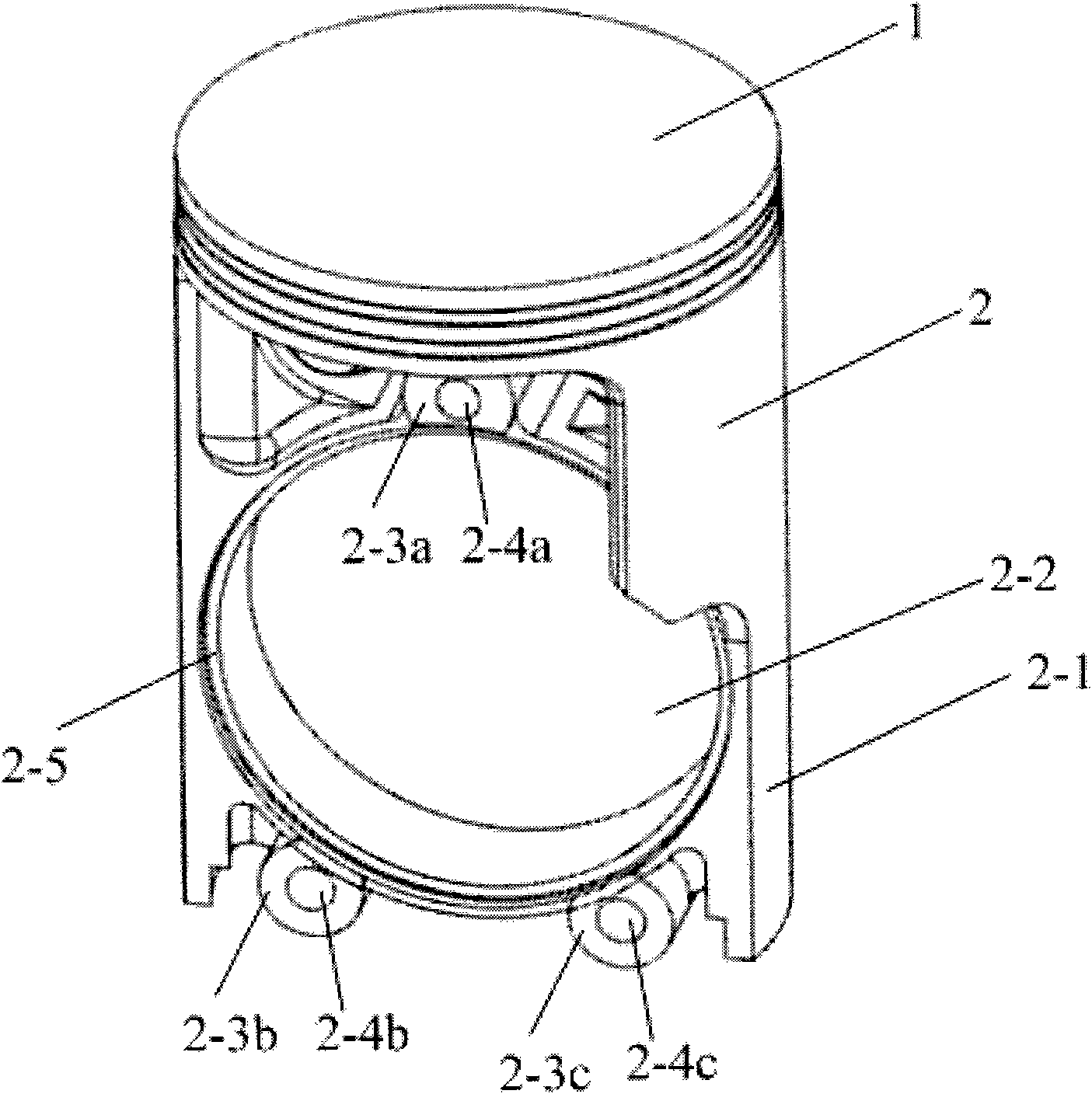
[0035] The piston seat 2 is provided with a circular slider accommodation hole 2-2, and the piston stopper 3 is detachably assembled on the edge of the end surface of the circular slider accommodation hole 2-2 and passes through the piston seat 2 the waist area. For example, in this embodiment, the piston stopper 3 is fixedly connected to the piston seat 2 through a connecting piece 4 ....
Embodiment 2
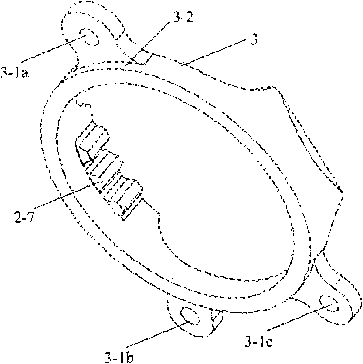
[0075] In this embodiment, the shape of the piston stopper 3 is along the figure 2 The arc baffles on the partial periphery of the circular slider accommodation hole 2-2 shown in . There are circular through holes at both ends of the arc-shaped baffle, and an outer stop (not marked) may also be provided on the side of the arc-shaped baffle facing the piston seat 2 .
[0076] The arc-shaped baffle can be assembled on the piston seat 2 of the piston in the same manner as in the above-mentioned embodiment 1.
[0077] The difference is that there are two arc-shaped baffles around each end surface of the circular slider accommodation hole 2-2 of the piston seat 2, which are symmetrically installed on the piston seat 2 to strengthen the Describe the strength of the waist of the piston seat 2.
[0078] On each arc-shaped blocking piece on the periphery of any end surface of the said circular slider accommodating hole 2-2, the same tooth segment as the inner tooth segment 2-7 descr...
Embodiment 3
[0082] In this embodiment, the piston stoppers are also arc-shaped stoppers, and circular through holes are respectively arranged at both ends of each arc-shaped stopper. figure 2 Two arc-shaped baffles are respectively installed on the periphery of each end surface of the circular slider accommodating hole 2-2 of the piston seat 2 shown. On each arc-shaped blocking piece on the periphery of any end face of the said circular slider accommodating hole 2-2, the same tooth segment as the internal tooth segment 2-7 described in the above-mentioned embodiment 1 (the exceptions). Of course, internal tooth segments may also be provided on all the arc-shaped blocking pieces on the periphery of the two end surfaces of the accommodating hole 2-2 of the circular slider. All the features of the internal tooth segment in this embodiment can be the same as those in Embodiment 1, and will not be repeated here.
[0083] The difference from the second embodiment is that when the arc-shaped ...
PUM
 Abstract
Description
Claims
Application Information
 - R&D
- Intellectual Property
- Life Sciences
- Materials
- Tech Scout
- Unparalleled Data Quality
- Higher Quality Content
- 60% Fewer Hallucinations
Browse by: Latest US Patents, China's latest patents, Technical Efficacy Thesaurus, Application Domain, Technology Topic, Popular Technical Reports.
© 2025 PatSnap. All rights reserved.Legal|Privacy policy|Modern Slavery Act Transparency Statement|Sitemap|About US| Contact US: help@patsnap.com


