
Lighting device for display apparatus and display apparatus

A technology for a display device and a lighting device, which is applied to the lighting device, the parts of the lighting device, lighting and heating equipment, etc., can solve the problems of reduced stress intensity and difficulty in the installation of parts, and achieves the effect of simple structure and excellent quality.

Inactive Publication Date: 2010-02-10
SHARP KK
View PDF1 Cites 0 Cited by
  • Summary
  • Abstract
  • Description
  • Claims
  • Application Information

AI Technical Summary

Problems solved by technology

However, on the other hand, the recessed portion (protruding portion) is formed at a constant width than the lamp diameter throughout the entire bottom surface of the storage member (chassis), so the strength of the storage member, especially with respect to the twisting direction of the storage member, is limited. The intensity of the stress is significantly reduced
Furthermore, a wide recessed portion is formed over the entire bottom surface of the storage member, thereby making it difficult to install various parts when the device is assembled.

Method used


Image

  • Lighting device for display apparatus and display apparatus
  • Lighting device for display apparatus and display apparatus
  • Lighting device for display apparatus and display apparatus

Examples


Embodiment approach 1

[0060] refer to Figure 1 ~ Figure 3 , Embodiment 1 of the present invention will be described.

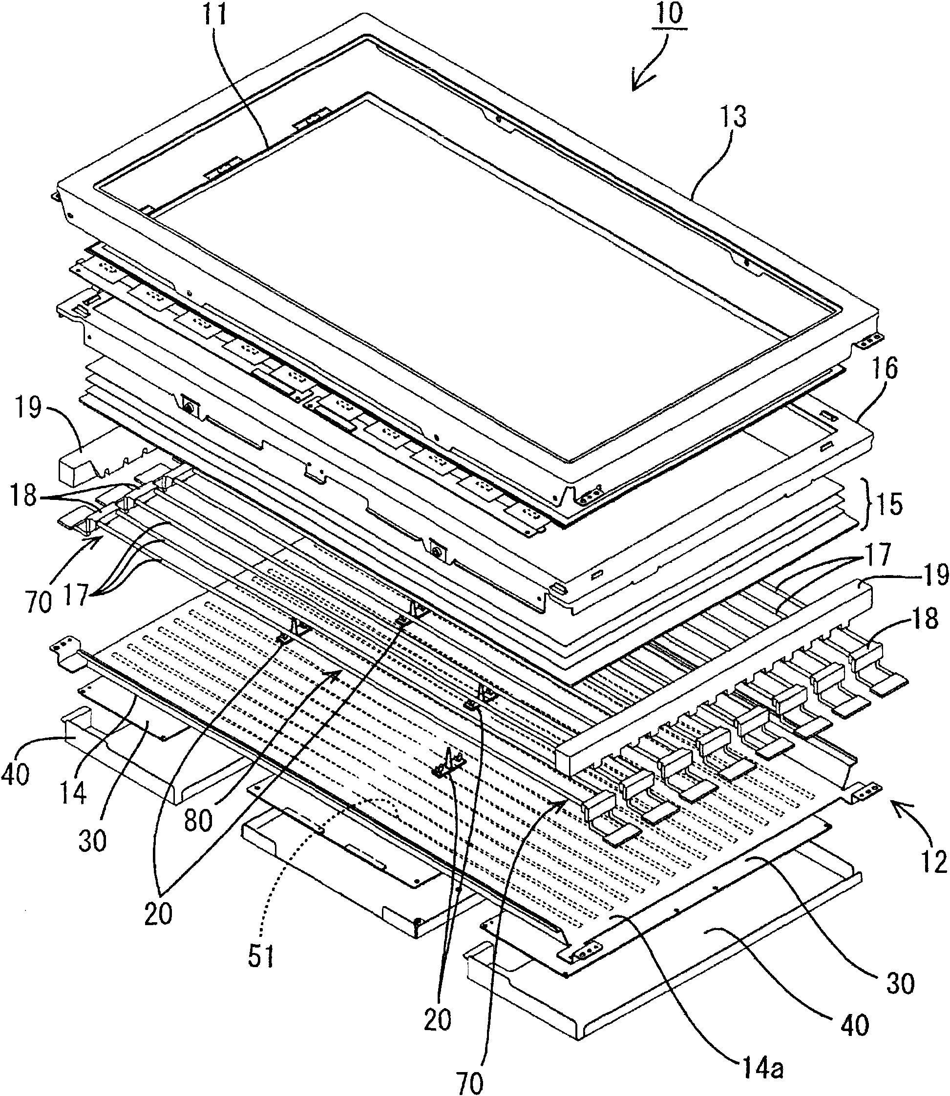
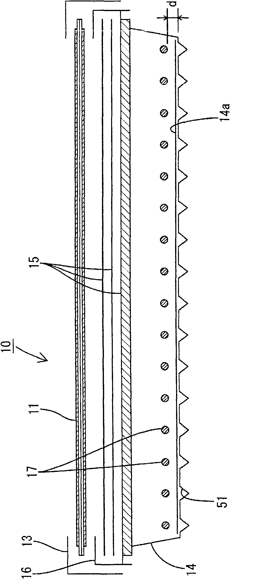
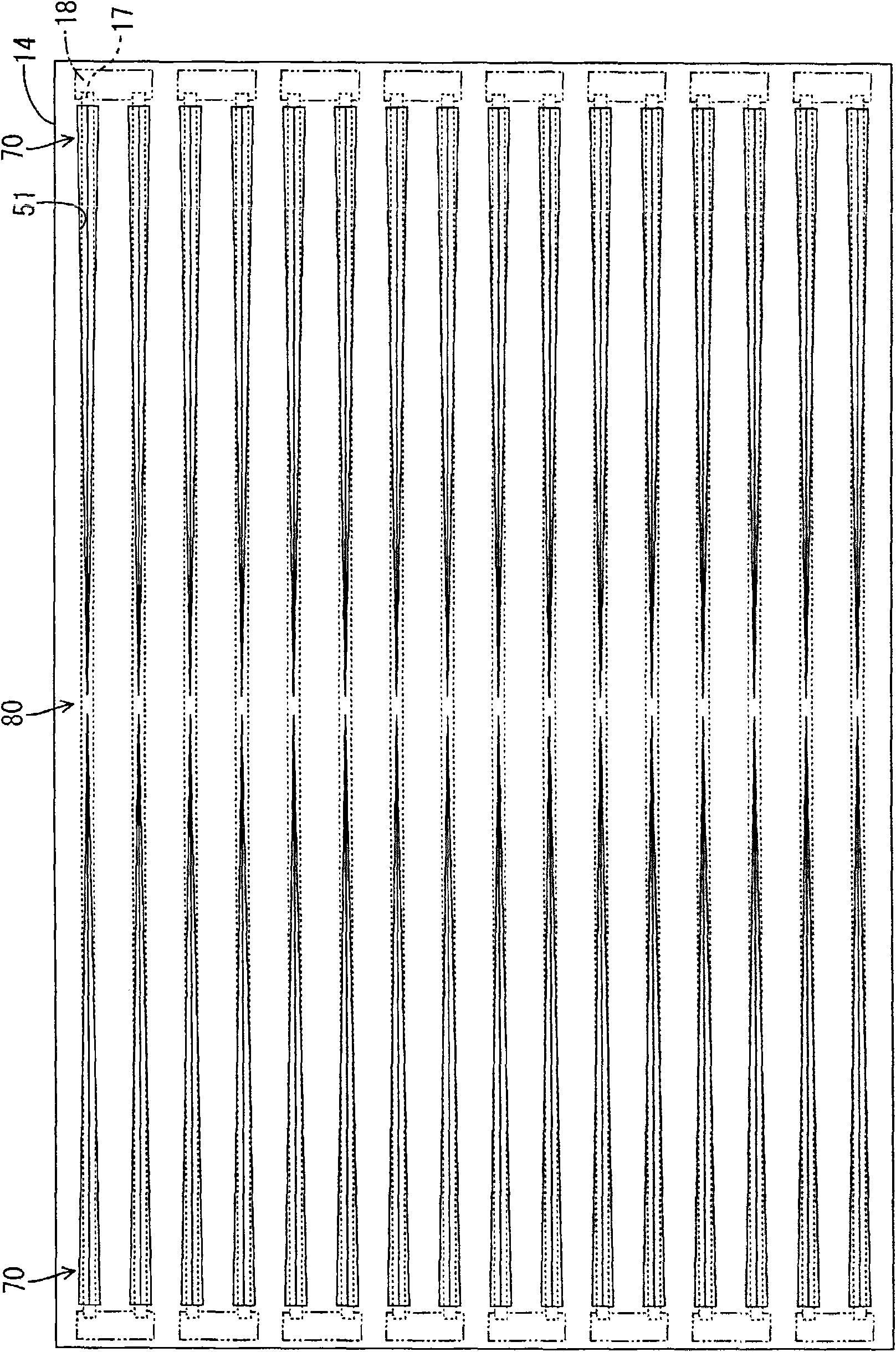
[0061] figure 1 It is an exploded perspective view showing a schematic configuration of the liquid crystal display device of the present embodiment; figure 2 is a cross-sectional view showing a schematic structure of the same liquid crystal display device; image 3 It is a plan view showing a schematic structure of a backlight chassis (chassis).

[0062] First, the overall configuration of the liquid crystal display device (display device) 10 of the present embodiment will be described. Such as figure 1 and figure 2 As shown, a liquid crystal display device 10 includes a rectangular liquid crystal panel 11 and a backlight device (display device lighting device) 12 that is an external light source, and these are integrally held by a frame 13 or the like. Among them, the liquid crystal panel 11 has a structure in which a pair of glass substrates are bonded with a predetermin...

Embodiment approach 2

[0090] refer to Figure 9 ~ Figure 12 Embodiment 2 of the present invention will be described. The difference from Embodiment 1 above is that the base 14 does not have a groove but an opening. Other than that, it is the same as the above-mentioned embodiment. The same reference numerals are assigned to the same parts as those in the above-mentioned embodiment, and overlapping descriptions will be omitted.

[0091] in addition, Figure 9 is an exploded perspective view showing a schematic configuration of a liquid crystal display device according to this embodiment, Figure 10 It is a sectional view showing the schematic structure of the same liquid crystal display device, Figure 11 It is a plan view showing a schematic structure of a backlight chassis (chassis), Figure 12 It is a perspective view showing separately the sheets attached to the backlight chassis.

[0092] The cold cathode tube 17 has the following structure. It is made into a long and thin tube shape (wir...


PUM


Abstract

Lighting device (12) for display apparatus characterized in that it includes light source (17) and chassis (14) covering the light source (17), the chassis (14) right under the light source (17) provided with groove portion (51) or opening portion (61), the groove portion (51) or opening portion (61) structured so that the width thereof is smaller right under low-voltage area (80) of the light source than right under high-voltage area (70) of the light source (17).

Description

technical field [0001] The present invention relates to a lighting device for a display device and a display device using the lighting device for a display device. Background technique [0002] A display device using a non-luminous optical element typified by a liquid crystal display device is provided with a backlight device on the back of the display panel in order to irradiate light to a display panel such as a liquid crystal panel (for example, refer to Patent Document 1). [0003] Patent Document 1: Japanese Patent Laid-Open No. 2006-66360 [0004] Patent Document 1 discloses a backlight unit including a lamp and a housing member for housing the lamp. However, in a backlight unit including such a lamp and a storage member for accommodating the lamp, when the lamp is dimmed, humming noise may be generated due to the second and third harmonics of the dimming frequency. [0005] Various factors are considered as the cause of such buzzing sound, for example, leakage curre...

Claims


Application Information

Patent Timeline
Patent Type & Authority Applications(China)
IPC IPC(8): F21S2/00H05B41/24F21V23/00F21Y103/00
CPCG02F1/133604H05B41/02G02F1/133608
Inventor 荒井政广
Owner SHARP KK
Learn More