Storage battery, storage battery receiving device, storage battery charging device, and usage fee settlement device for storage battery

一种充电装置、收纳装置的技术,应用在电池电路装置、电池/电池的牵引、二次电池充电/放电等方向,能够解决更换动作不简单等问题,达到消减二氧化碳气体、构造简单、防止地球温室效应的效果

Inactive Publication Date: 2010-02-10
石井见敏
View PDF2 Cites 23 Cited by
  • Summary
  • Abstract
  • Description
  • Claims
  • Application Information

AI Technical Summary

Problems solved by technology

The technology of Patent Document 3 itself has rail-shaped electrode connection parts corresponding to the positive and negative electrodes of the storage battery, and there is also a problem that the replacement operation is not easy.

Method used


Image

  • Storage battery, storage battery receiving device, storage battery charging device, and usage fee settlement device for storage battery
  • Storage battery, storage battery receiving device, storage battery charging device, and usage fee settlement device for storage battery
  • Storage battery, storage battery receiving device, storage battery charging device, and usage fee settlement device for storage battery

Examples


Embodiment approach 1

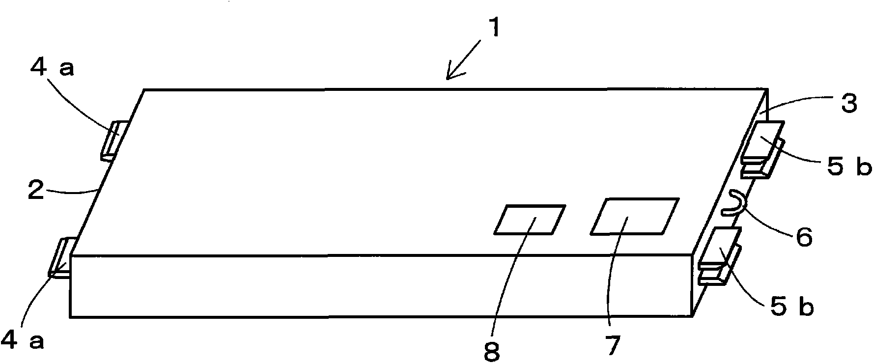
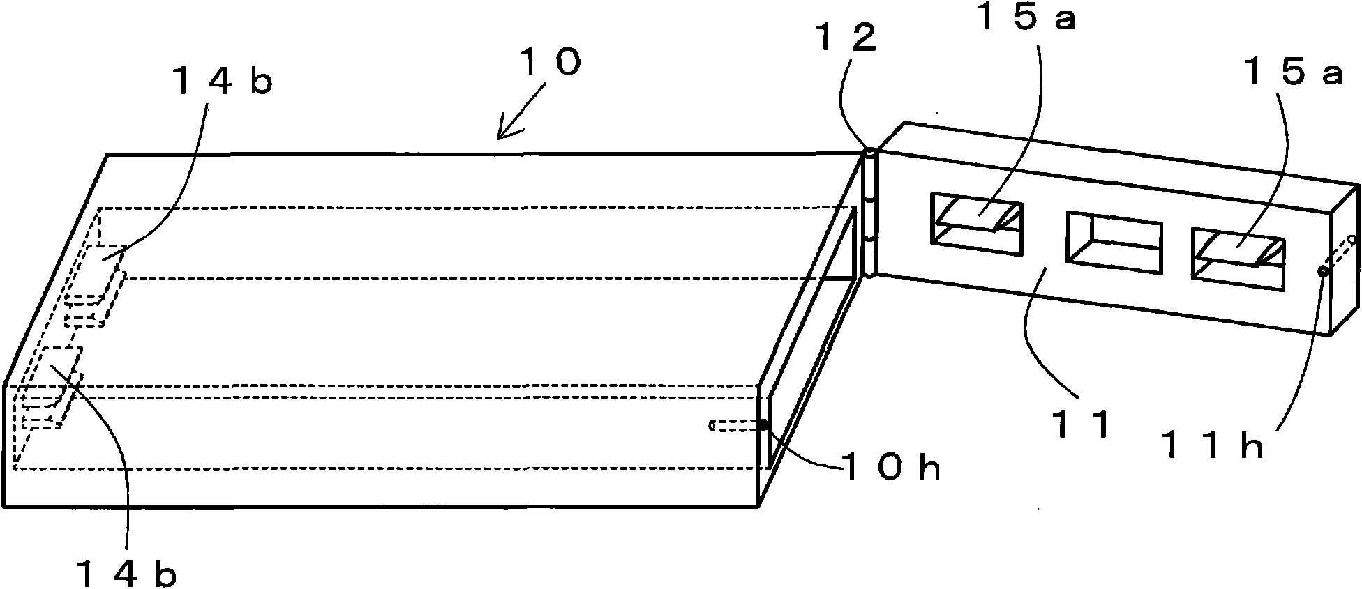
[0066] based on Figure 6 , 7 and 8 describe other embodiment 1 of the present invention.

[0067] Figure 6 It is a schematic external view showing another storage battery according to the present invention in perspective, and it is different from that of the above-mentioned embodiment. figure 1 quite. in addition, Figure 7 It is a three-dimensional enlarged partial appearance view of the main body of the battery storage device for inserting and storing the battery of the present invention, which is different from that of the above-mentioned embodiment. Figure 5 quite. Figure 8 It is an enlarged three-dimensional partial external view showing the main body of the battery storage device for inserting the battery of the present invention.

[0068] In the above-described embodiment, the battery is merely fixed to the main body and the lid of the battery storage device with bolts. Therefore, there is a possibility that the lid portion may be opened due to the loosening ...

Embodiment approach 2

[0083] based on Figure 9 as well as Figure 10 Another embodiment 2 of the present invention will be described. Here, in this other second embodiment, the same parts as those in the above-mentioned embodiment are assigned the same symbols and detailed description thereof will be omitted.

[0084] Figure 9 It is a schematic external view showing a storage battery according to another embodiment 2 of the present invention in perspective, and corresponds to that of the above-mentioned embodiment. figure 1 . in addition, Figure 10 It is an enlarged three-dimensional view showing a partial appearance of the main body of the battery storage device for inserting the battery of the present invention, which corresponds to the above-mentioned embodiment. Figure 5 .

[0085] In Embodiment 1 described above, the insertion terminals of the positive electrode are juxtaposed and projected on the front side, and the clamp terminals of the negative electrode are juxtaposed and protru...


PUM


Abstract

Provided are a storage battery used for an electric automobile etc. and capable of being replaced in a very short time and by simple work, and a storage battery receiving device. The storage battery (1) is constructed from a flat plate-like insertion terminal protruded from one side face of the storage battery having a substantially rectangular parallelepiped shape, and from a holding terminal protruded from the other side face of the storage battery and constructed from plate-like members that are parallel to each other so as to be able to hold an insertion terminal, and this construction facilitates replacement of the storage battery. Alternatively, the storage battery has a set of two or more of such insertion terminals and a set of two or more of such holding terminals that are arranged on the respective side faces. The storage battery has a display device (7) capable of displaying the amount of electric power charged, the amount of electric power consumed, the amount of residual electric power, and one or more kinds of data selected from storage battery temperature, and also has a data output section for outputting the data to the control device side of an automobile.

Description

technical field [0001] The present invention relates to a large-scale and high-capacity storage battery used in electric vehicles and the like, a storage device for the storage battery, a charging device for the storage battery, and a settlement device for the usage of the storage battery. Specifically, it relates to a storage battery, a storage battery storage device, a storage battery charging device, and a storage battery usage accounting device capable of replacement and usage settlement in a very short time and with simple operations. Background technique [0002] The reduction of carbon dioxide gas has been advocated as one of the countermeasures against the global warming effect, and measures have been promoted. In addition, it is generally believed that if electric vehicles are used instead of internal combustion engine vehicles currently in use, it is possible to reduce the emission of carbon dioxide gas on the earth by one-half. That is, power plants and the like ...

Claims


Application Information

Patent Timeline
Patent Type & Authority Applications(China)
IPC IPC(8): H01M2/30B60L11/18B60R16/04B60S5/02G07F7/08H01M2/10H01M10/42H01M10/44B60L50/64G06Q20/10G06Q50/06H01M50/244H01M50/249H01M50/559
CPCB60L11/1877H01R13/113Y02T10/7072G06Q20/102H02J7/0027B60K2001/0455B60L11/1803Y02T10/7005B60L2200/26B60L11/1822H02J7/0045H01M2/1005B60K2001/0461H01M10/488Y02T90/124B60R16/04Y02E60/12Y02T10/7055Y02T90/128G06Q50/06Y02T90/14H01M10/486B60L2230/16H01M2/305B60K1/04Y02T10/705B60L11/1879H01M2/206H01M2/1083B60S5/06H01M2/1061Y02T10/7088Y02T90/163H02J7/00H01M10/441B60L50/51B60L53/80B60L50/66B60L50/64B60L53/305B60K2001/0422B60K2001/0433H02J2310/48H02J2310/46Y02T10/70Y02T90/12Y02T90/16Y02E60/10H01M50/256H01M50/249H01M50/559H01M50/244H02J7/0013B60S5/02B60L50/50
Inventor 石井见敏
Owner 石井见敏
Why Eureka
Try Eureka