
Deep-well centrifugal pump with two thrust bearing pairs on each impeller

A thrust bearing and centrifugal pump technology, which is applied to the components, pumps, and pump components of pumping devices for elastic fluids, can solve the problems of reduced pump efficiency, damage, limited ability to withstand axial forces, etc. The effect of long service life, simple solution and low manufacturing cost

Inactive Publication Date: 2010-02-17
JIANGSU UNIV +1
View PDF1 Cites 2 Cited by
  • Summary
  • Abstract
  • Description
  • Claims
  • Application Information

AI Technical Summary

Problems solved by technology

Generally, deep well centrifugal pumps use radial sealing rings and balance holes on the impeller to balance part of the axial force, and the remaining axial force is borne by the thrust bearing inside the motor. For deep well centrifugal pumps, the remaining axial force is sometimes very large. Large, and the thrust bearing in the submersible motor has limited ability to withstand axial force, so there is still the possibility of damage
The invention patent with the patent number ZL200610038596.X "a multi-stage centrifugal pump with self-balancing axial force of the impeller" adopts the method of reducing the diameter of the impeller rear cover plate to balance the axial force of the impeller, which has the defect of reducing the efficiency of the water pump, that is, to achieve the impeller For the automatic balance of the axial force, the diameter of the impeller rear cover must be greatly reduced, and the efficiency of the water pump will be significantly reduced at this time. The axial force acts on the end seal of the impeller, and when the well water contains sand, the end seal of the impeller will be damaged quickly

Method used


Image

  • Deep-well centrifugal pump with two thrust bearing pairs on each impeller

Examples


Embodiment Construction

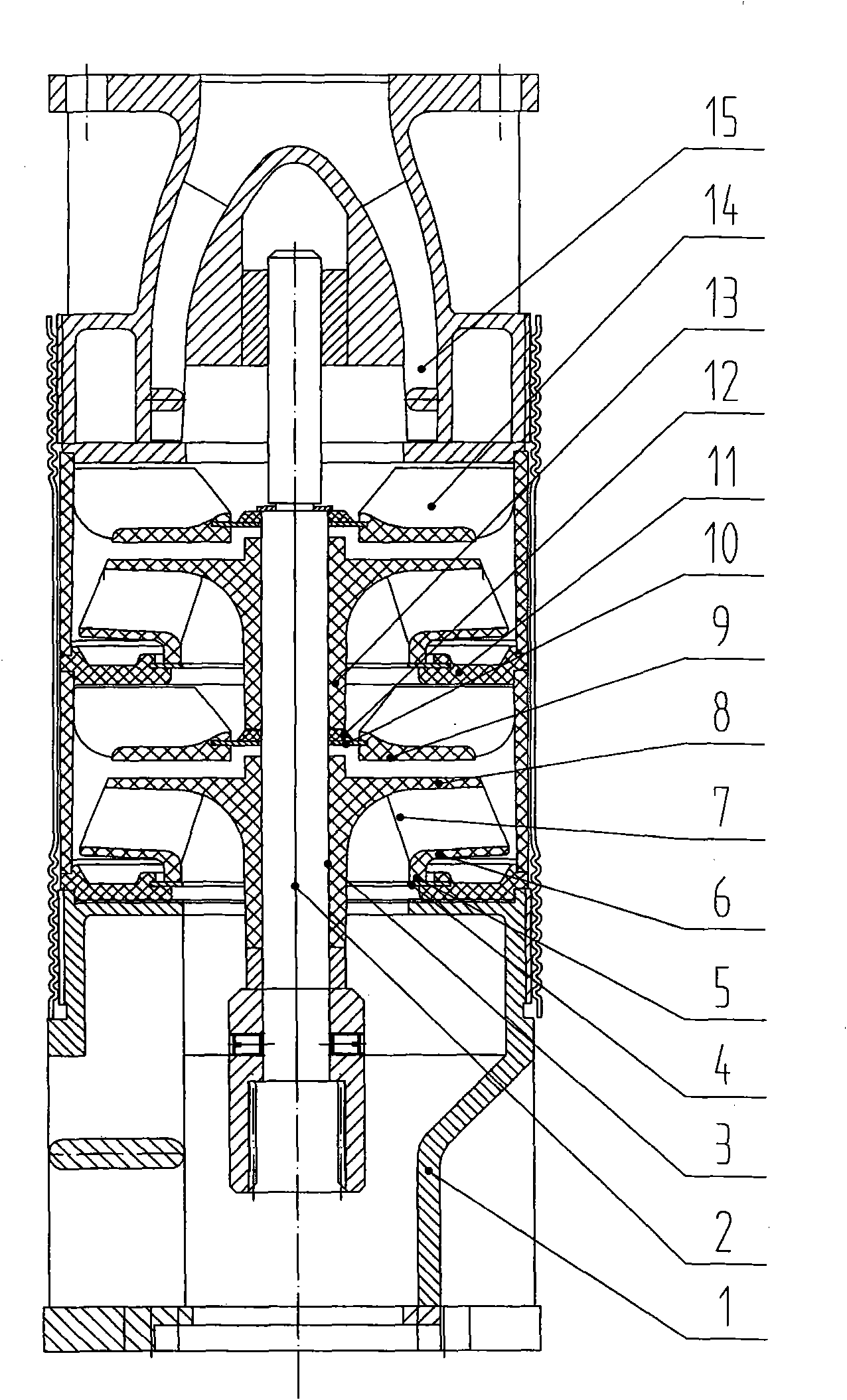
[0014] figure 1 The shown embodiment is a well submersible pump that an impeller 7 and a flow guide casing 14 are all made of engineering plastics, and it is also a deep well centrifugal pump, which consists of a two-stage impeller 7 and a flow flow casing 14 together with a water inlet section 1 and A water outlet section 15 is formed in series. The impeller 7 is a closed impeller with an impeller front cover 6 and an impeller rear cover 8. The diameter of the impeller rear cover 8 is smaller than that of the impeller front cover 6, and its axial force is higher than that of a conventional impeller. The impeller is lowered. The impeller inlet adopts end face seal, and the impeller inlet end face seal pair composed of the moving ring 5 of the impeller inlet end face seal and the static ring 4 of the impeller inlet end face seal is made of stainless steel plate and engineering plastic, which is also a thrust capable of bearing axial force The bearing pair, the impeller shaft h...


PUM


Abstract

The invention relates to a deep-well centrifugal pump with two thrust bearing pairs on each impeller. Each impeller is a closed impeller with a front cover plate and a rear cover plate; the diameter of the rear cover plate of the impeller is smaller than that of the front cover plate of the impeller; an inlet of the impeller adopts an end surface sealing way, and an end surface sealing pair at theinlet of the impeller is made into a thrust bearing pair capable of bearing axial force; an axial hole of the impeller is in clearance fit with a pump shaft; an impeller hub and a flow-guiding shellhub form a second thrust bearing pair; the lower end of the impeller hub is provided with wear-resistant rubber rotating together with the impeller hub; the upper end of the flow-guiding shell hub isprovided with a stainless steel flat plate integrated with a flow-guiding shell; and a contact surface between the wear-resistant rubber and the stainless steel flat plate is a bearing surface of thesecond thrust bearing pair. The invention has the advantages that the axial force of the impeller can be balanced and borne independently, the service life of the deep-well centrifugal pump is greatlyprolonged, and a solution is simple and reliable and needs low manufacture cost.

Description

Technical field [0001] The invention relates to a fluid machine for pumping deep well groundwater, in particular to a deep well centrifugal pump which needs to overcome axial force. Background technique [0002] At present, the known deep well centrifugal pumps all have serious axial force problems, because when the impellers are working, axial forces will be generated on the impellers. If there are more impellers in the deep well centrifugal pumps, the axial force problem will be serious. Generally, deep well centrifugal pumps use radial sealing rings and balance holes on the impeller to balance part of the axial force, and the remaining axial force is borne by the thrust bearing inside the motor. For deep well centrifugal pumps, the remaining axial force is sometimes very large. Large, and the thrust bearing in the submersible motor has limited ability to withstand axial force, so there is still the possibility of damage. The invention patent with the patent number ZL2006...

Claims


Application Information

Patent Timeline
IPC IPC(8): F04D1/06F04D29/22F04D29/66
Inventor 陈贤元陆伟刚李振同周岭
Owner JIANGSU UNIV
Features
  • Generate Ideas
  • Intellectual Property
  • Life Sciences
  • Materials
  • Tech Scout
  • Unparalleled Data Quality
  • Higher Quality Content
  • 60% Fewer Hallucinations
Learn More