Mini fan

A technology of micro fans and air inlets, which is applied to electromechanical devices, electrical components, liquid fuel engines, etc., can solve the problems of the direction design of micro fans that are not easy to miniaturize, and the overall volume of the fans can be reduced.

Active Publication Date: 2010-02-17
SUNONWEALTH ELECTRIC MACHINE IND
View PDF0 Cites 1 Cited by
  • Summary
  • Abstract
  • Description
  • Claims
  • Application Information

AI Technical Summary

Problems solved by technology

[0005] In order to improve the above-mentioned shortcomings that the existing micro fans are not easy to design in the direction of miniaturization, the present invention provides a micro fan, which can effectively reduce the overall volume of the fan without reducing the air output, which is the main purpose of the invention

Method used


Image

  • Mini fan
  • Mini fan
  • Mini fan

Examples


Embodiment Construction

[0035] In order to make the above-mentioned and other objects, features and advantages of the present invention more comprehensible, the preferred embodiments of the present invention are specifically cited below, together with the accompanying drawings, as follows:

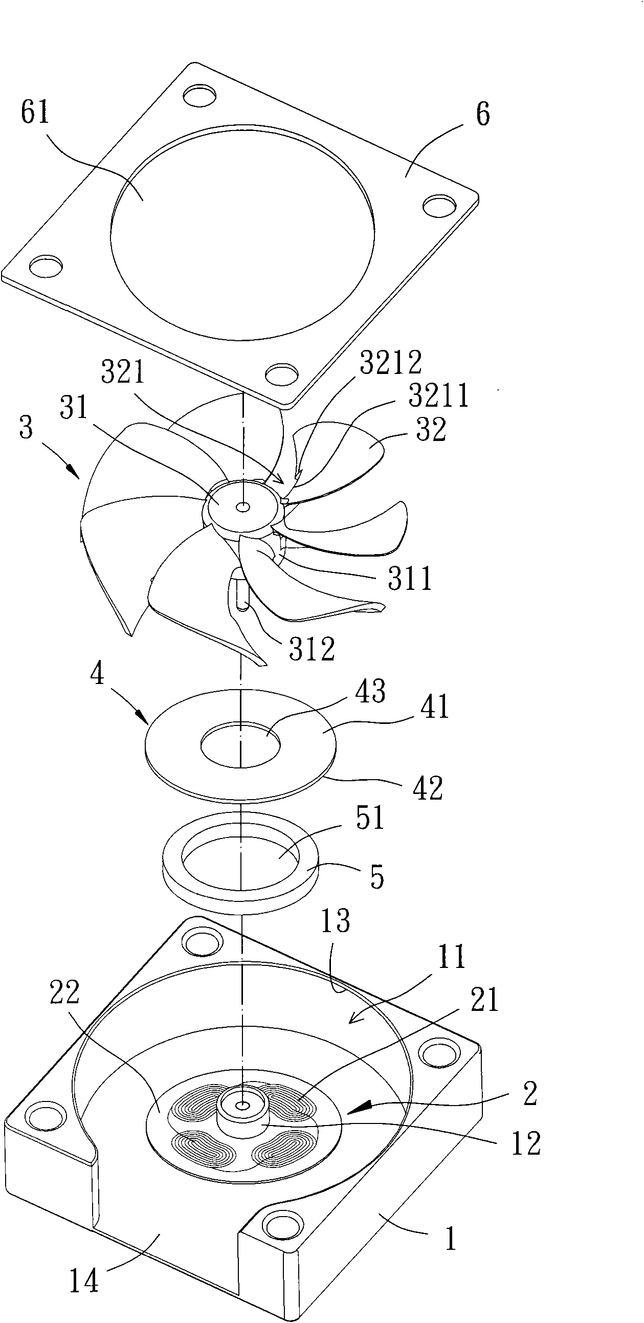
[0036] Please refer to image 3 , 4 As shown, the micro fan according to the first embodiment of the present invention includes a base 1 , a stator 2 , a rotor 3 , a sealing magnet 4 , a permanent magnet 5 and an upper cover 6 . in:

[0037] The base 1 has an accommodating space 11, a shaft tube 12 is arranged in the accommodating space 11, and a bearing is preferably arranged in the shaft tube 12; An opening 13 in the space 11 and an air outlet 14 on one side.

[0038] The stator 2 is arranged in the accommodating space 11 of the base 1, and the stator 2 is provided with a coil group 21, and the coil group 21 is preferably arranged on a substrate 22 in a wiring manner, so as to further reduce the size of the ...


PUM


Abstract

The invention discloses a mini fan, which comprises a substrate, a stator, a rotor, a sealing magnetic sheet and a permanent magnet. The stator is arranged in the substrate; the rotor is provided withan axial seat of which the peripheral face is provided with a plurality of blades; the sealing magnetic sheet is provided with a first combining surface and a second combining surface; the first combining surface of the sealing magnetic sheet combines with hemlines of each blade; and the permanent magnet combines with the second combining surface of the sealing magnetic sheet and is opposite to the stator. Thus, the overall volume of the mini fan can be reduced effectively without reducing the amount of air output.

Description

technical field [0001] The invention relates to a fan, in particular to a blower type miniature fan with a side air outlet function. Background technique [0002] Please refer to figure 1 , 2 As shown, the conventional blower fan 9 includes a base 91 , a stator 92 , a rotor 93 and a cover 94 . The base 91 is a hollow shell, and the side and the top of the base 91 respectively have a side air outlet 911 and an opening 912; the stator 92 is combined in the base 91; the rotor 93 includes a hub 931, a metal ring 932 and a permanent magnet 933, a spoke plate 934 and several blades 935, the hub 931 is rotatably combined in the base 91, the metal ring 932 is combined on the inner peripheral surface of the hub 931, The permanent magnet 933 is combined with the inner peripheral surface of the metal ring 932, so that the metal ring 932 can be interposed between the hub 931 and the permanent magnet 933 to provide a magnetic effect, and the web 934 is separated from the hub The oute...

Claims


Application Information

Patent Timeline
Patent Type & Authority Applications(China)
IPC IPC(8): F04D29/60F04D29/30F04D29/00H02K1/27H02K7/14
Inventor 洪银树尹佐国
Owner SUNONWEALTH ELECTRIC MACHINE IND
Why Eureka
Try Eureka