
Invariance identification method based on characteristic point and homography matching

A recognition method and a homography technology, applied in the fields of image understanding, computer vision, and pattern recognition, to achieve rapid and accurate object recognition, reduce computing resource consumption, and improve computing efficiency

Inactive Publication Date: 2010-02-17
FUDAN UNIV
View PDF0 Cites 14 Cited by
  • Summary
  • Abstract
  • Description
  • Claims
  • Application Information

AI Technical Summary

Problems solved by technology

Identify all planes one by one

Method used


Image

  • Invariance identification method based on characteristic point and homography matching
  • Invariance identification method based on characteristic point and homography matching
  • Invariance identification method based on characteristic point and homography matching

Examples


Embodiment Construction

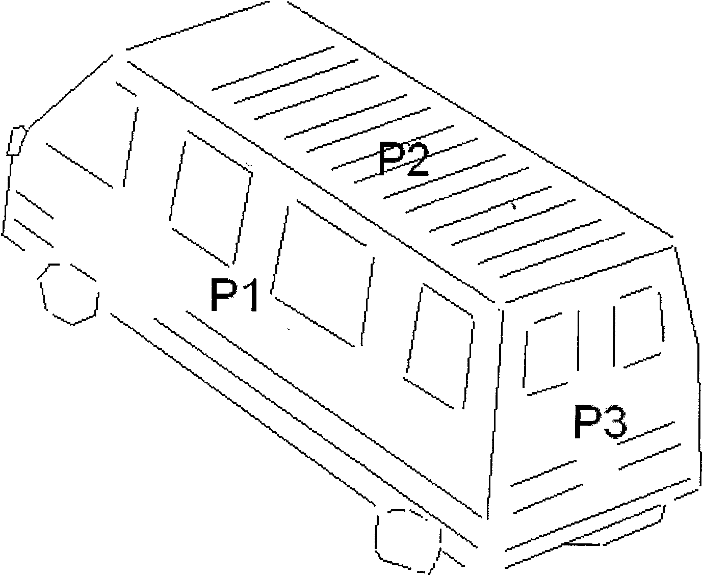
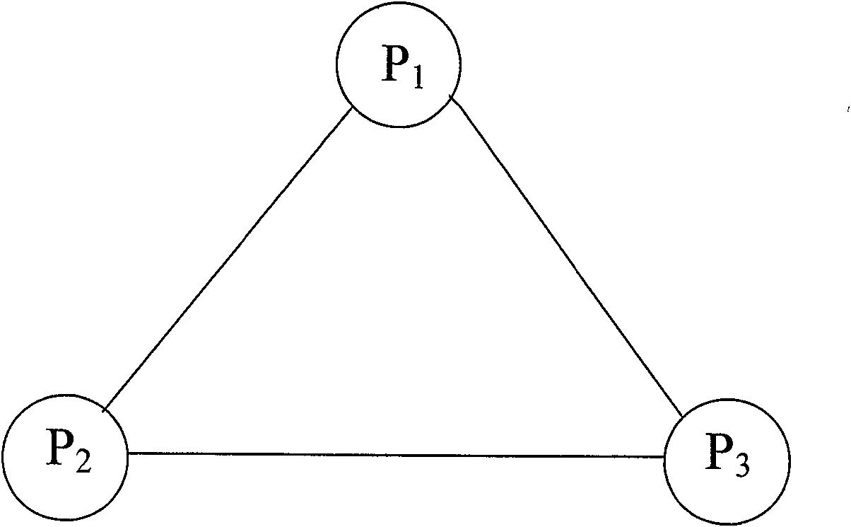
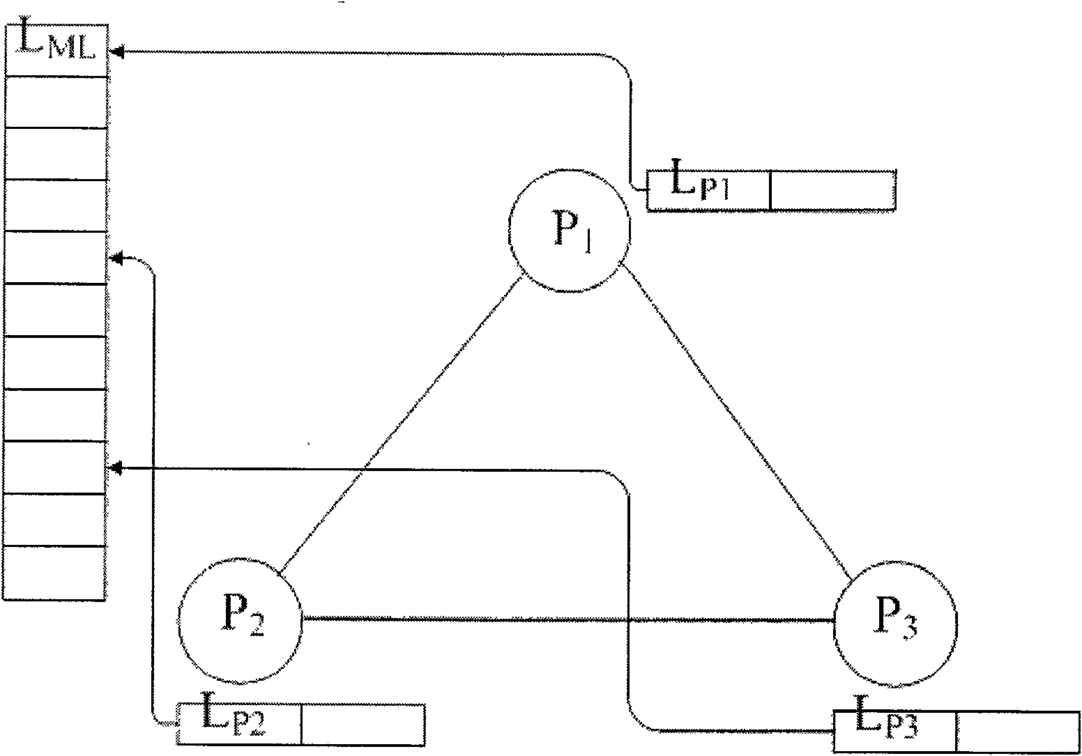
[0070] The present invention will be further described in conjunction with the accompanying drawings and embodiments. Now take the model shown in FIG. 1 as an example to specifically describe the invariance identification method of the present invention.

[0071] 1. Implementation of 3D model definition

[0072] An image (a) of a car model with three visible faces can be described as a (b) structure, as shown in Figure 1. For the long contour line set L in the model image ML For each straight line segment in , we need to indicate the plane where it is located. Let each plane P k Both maintain a straight line group L Pk , while L Pk Each element in is pointing to L ML A straight line segment in , means that the straight line belongs to this plane, as shown in (c) of Figure 1.

[0073] Suppose there are K planes in total, and there are L ML =L P1 ∪L P2 ∪…∪L PK . L ML Some straight line segments in may have multiple pointers at the same time, because it may be the in...


PUM


Abstract

The invention provides an invariance identification method based on characteristic point and homography matching. The invention adopts a hypothesis testing method, analyzes the invariance characteristic in a scene image under the condition of knowing the line characteristic and position relation of each plane of a model, and supposes matching of some line sections so as to obtain the matching relation of certain plane and calculate the homography thereof. Then, the model plane is mapped to a scene, and hypothesis is verified by using the matching of the line section in the plane. All planes are respectively recognized. At last, the accuracy of the hypothesis is verified by the invariance between planes. Compared with the traditional hypothesis verification method, the method of the invention scatters the solving of overall situation coordinate system change in the hypothesis verification method into the solving of homography change of each plane, which lowers solving complexity and canquickly and accurately recognize objects.

Description

technical field [0001] The invention belongs to the field of pattern recognition, computer vision and image understanding, and recognizes the artificial object based on the feature of the straight line segment by matching the straight line segment in the scene and the model image. Background technique [0002] 3D object recognition is one of the most active research fields in the field of computer vision, playing a central role in a large number of real-world fields such as robot control, automatic navigation, automatic inspection, assembly tasks and analysis of medical images. For example, precision-guided weapons need to use 3D object recognition technology to identify and track attack targets, and assembly or packaging robots need to use 3D object recognition technology to locate the posture of products. The existing 3D object recognition technology is mainly a process of using the input scene image data to obtain the expression of the scene features, and then matching th...

Claims


Application Information

Patent Timeline
IPC IPC(8): G06K9/00G06K9/62G06T7/00
Inventor 危辉裘禛宇
Owner FUDAN UNIV
Learn More