

Method and device for the production of moulded pieces from a layer of polyurethane
A polyurethane layer and molded parts technology, which is applied in the direction of spraying device, liquid spraying device, coating, etc., can solve the problem of adding reaction mixture to the coating mechanism or spraying mechanism, and achieve low consumption of raw materials, small cycle time and fast cycle time The best effect
- Summary
- Abstract
- Description
- Claims
- Application Information
AI Technical Summary
Problems solved by technology
Method used
Image

Examples
Embodiment Construction
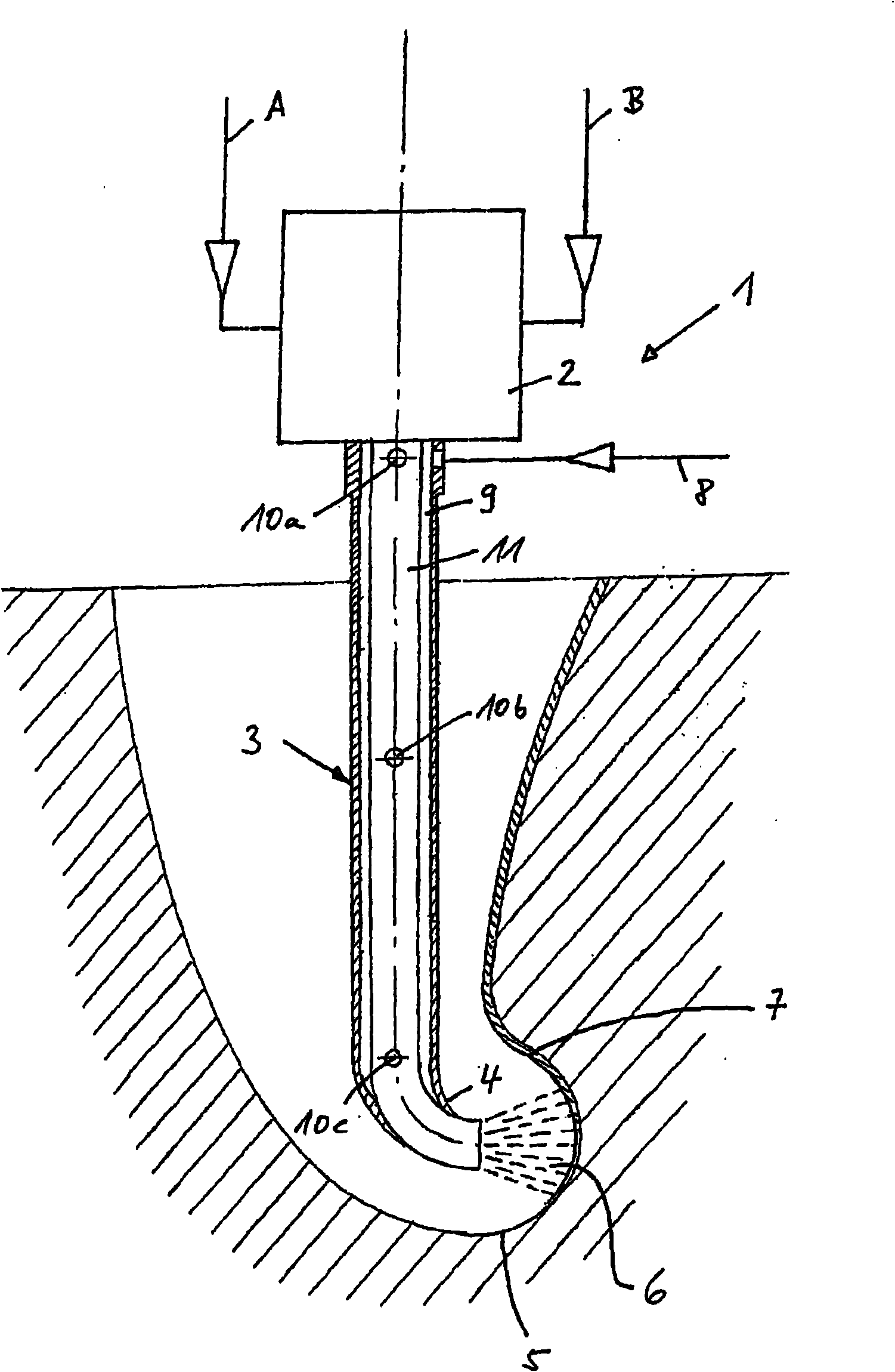
[0093] exist figure 1 A device 1 with a mixing head 2 and a spray nozzle 3 (which acts as a spray device comprising an arc 4 of 90°) is shown for spraying the polyurethane reaction mixture onto a substrate 5. The reaction components polyol A and isocyanate B are conveyed from a storage container via a metering device (not shown in the schematic diagram) via connecting pipes to a high-pressure mixing head 2 where they are mixed with one another. Next, the reaction mixture is extruded through the flow channel of the spray nozzle 3 (with an arc of 90°) and is applied in the jet 6 on the substrate 5, which here means has distinct dimples and inverted The tool surface of a tool with recesses (i.e. inaccessible pockets).
[0094] The sprayed reaction mixture reacts on the tool surface (substrate 5) to produce a skin 7, which can then be post-foamed in a subsequent processing step (not shown in the diagram), or can be further e.g. Processed into shaped parts for the automotive indu...
PUM
 Abstract
Description
Claims
Application Information